4-19 Installation
AC30V Variable Speed Drive
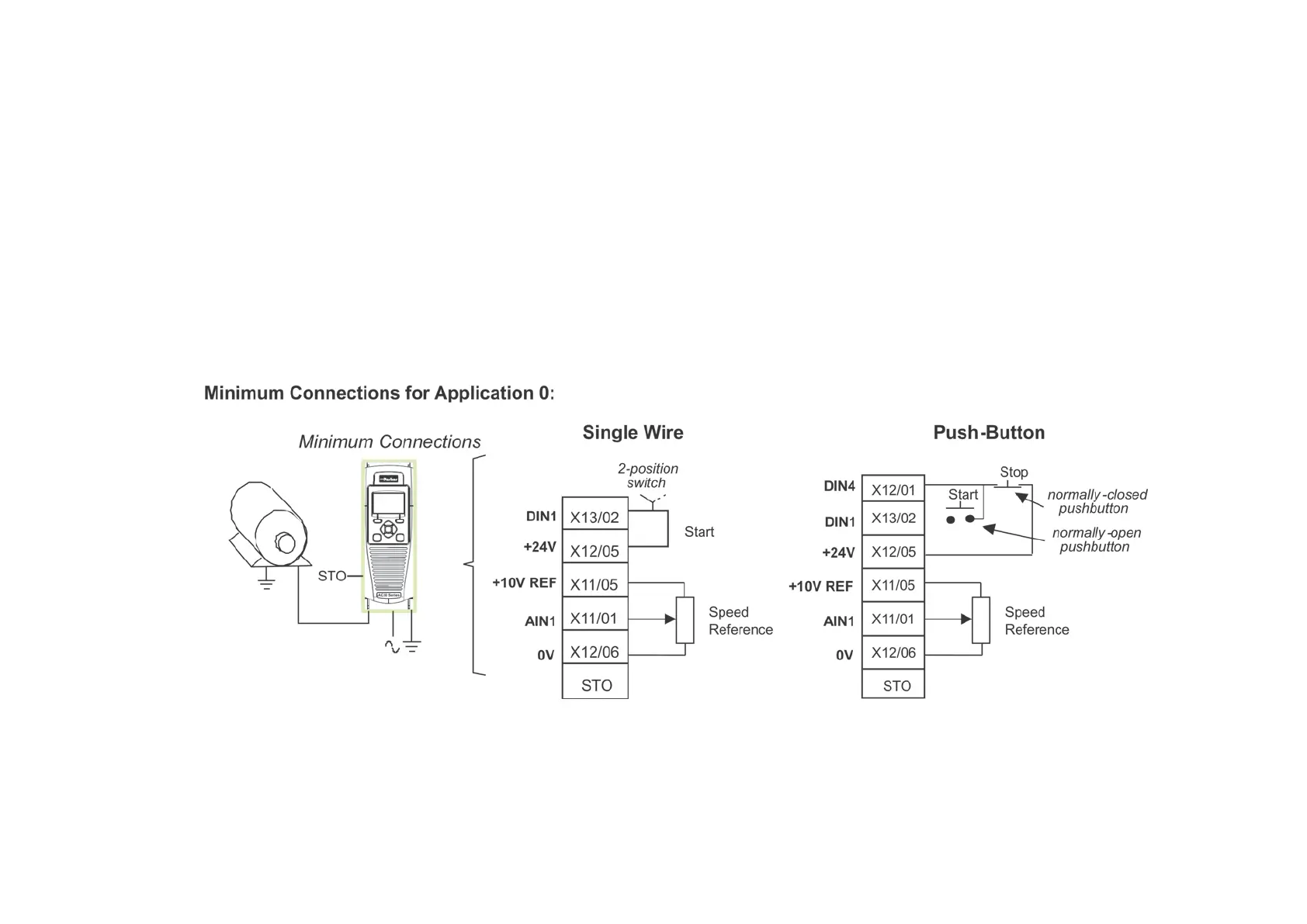
The diagram below shows the minimum connections to operate the drive for single-wire (switch) starting, and push-button starting. Other control
connections for your Application, can be made to suit your system.
Referring to the Connection Diagram:
• Follow the instructions for Local Control Wiring, as detailed above
• Install using minimum connections (suitable for Application 0 only), or refer to the appropriate control wiring for your system.
Note: You can still operate the drive in Local mode, if necessary, with any Application selected.
This application is ideal for general purpose applications. It provides push-button or switched start/stop control. The setpoint is the sum of the
two analogue inputs AIN1 and AIN2, providing Speed Setpoint + Speed Trim capability.

 Loading...


