Vacuum spray degassing — 24.04.2020 - Rev. A
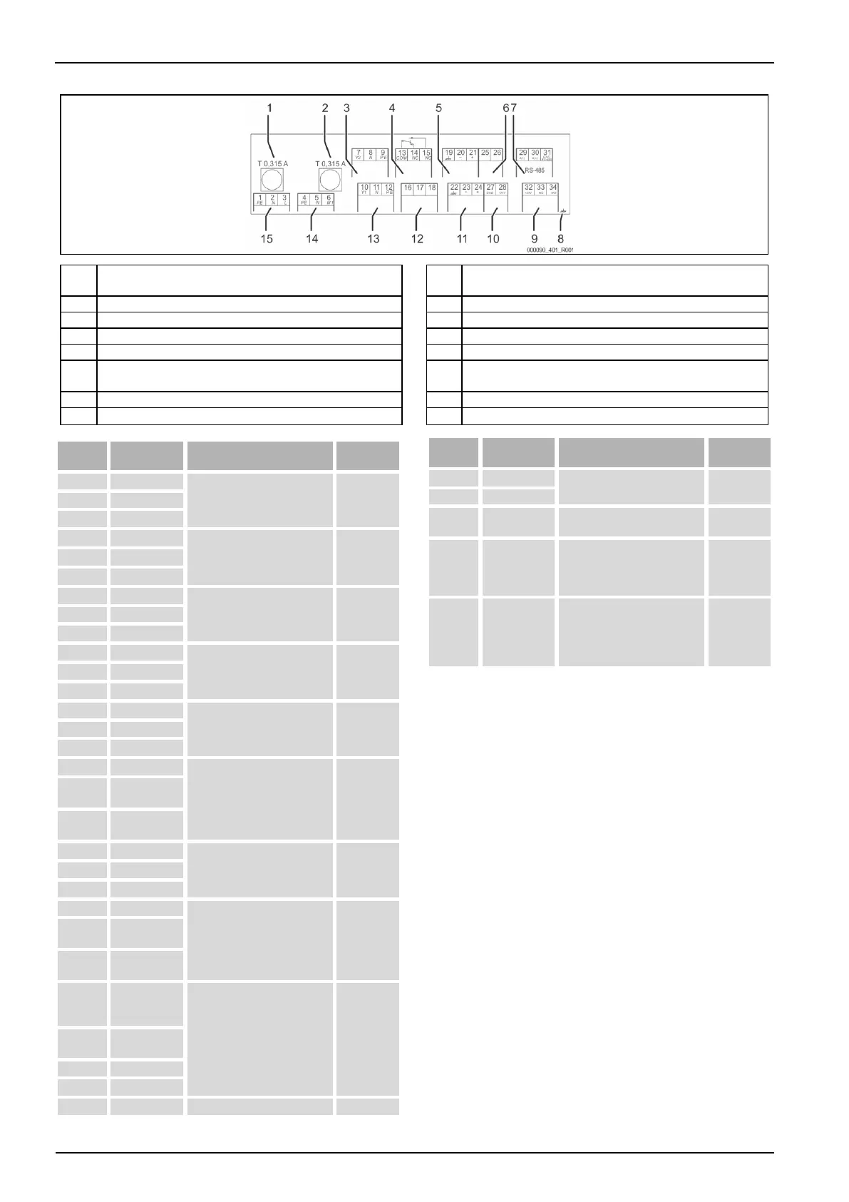
6.5.1 Terminal diagram
Digital inputs:
Water meter; Insufficient water
Fuse for motorized ball valve
Ball control valve (supply)
CD degassing control valve
External make-up demand (Levelcontrol only)
Optional for conductivity
Ball control valve
(correcting variable (25) / Return value (46))
230 V power supply via mains
cable and plug.
CD degassing control valve
Group message (floating).
External make-up demand from
a pressurisation station;
controller must be set to
"Levelcontrol"!
Level analogue input, not used
by the device.
0 – 10 V
(correcting
variable)
Insufficient water switch - dry-
running protection
Contact water meter, for
evaluation of the make-up,
terminal 32/33 closed = meter
pulse.
Insufficient water switch, contact
32/34. Lead the cable of the
insufficient water switch through
the cable gland and connect at
the terminals
6.5.2 RS-485 interface
6.5.2.1 Connecting the RS-485 interface
Connect the interface as follows:
1. For connecting the interface use only a cable with these properties:
– LJYCY (TP), 4 × 2 × 0.8, maximum overall bus length 1000 m.
2. Use a shielded cable to connect the interface to terminals 29, 30, 31 of the
main board in the control cabinet.
– For connecting the interface, see chapter 6.5 "Elektrischer Anschluss"
on page 10 .
3. When using the device with a control centre not supporting an RS-485
interface (RS-232, for example), you must use a corresponding adapter.
 Loading...