Vacuum spray degassing — 24.04.2020 - Rev. A
Risk of burns on hot surfaces
Hot surfaces in heating systems can cause burns to the skin.
• Wait until hot surfaces have cooled down or wear protective safety gloves.
• The operating authority is required to place appropriate warning signs in
the vicinity of the device.
Risk of injury due to pressurised liquid
If installation, removal or maintenance work is not carried out correctly, there is a
risk of burns and other injuries at the connection points, if pressurised hot water
or hot steam suddenly escapes.
• Ensure proper installation, removal or maintenance work.
• Ensure that the system is de-pressurised before performing installation,
removal or maintenance work at the connection points.
The ’Servitec’ must be serviced annually or after 16,000 degassing intervals,
whichever comes first.
Note!
Shorter maintenance intervals are required if the default setting for
interval degassing of 8 degassing cycles and 12 h idling time exceeds
the following times for continuous degassing:
• Continuous degassing time of about 14 days
or
• Continuous degassing time of 7 days + 1 year interval degassing
with default setting.
The maintenance intervals depend on the operating conditions and the
degassing times.
The annual maintenance is displayed upon expiry of the set operating time. Use
"Quit" to acknowledge the "Maintenance recommended" message.
Note!
Maintenance work must be carried out and confirmed by specialist
personnel or the Reflex Customer Service.
The maintenance schedule is a summary of maintenance tasks to be carried out
regularly.
▲ = Check, ■ = Service, ● = Clean
Check for leaks, see chapter 9.1
"Exterior leak test" on page 39.
• "PU" pump
• Screw connections
• "DV" degassing valve
Vacuum function test.
– see chapter 7.6 "Vacuum test" on
page 33
Clean the dirt trap.
– see chapter 9.2 "Cleaning the dirt
trap" on page 39
Depending on
the operating
conditions
Check the controller settings.
Function test.
• "SE" system degassing
• Make-up degassing "NE"
see chapter 9.3 "Inspecting
system degassing and make-up
degassing" on page 39
When operating with water/glycol
mixtures
• Control of the mixing ratio.
• If necessary, adjust according to
manufacturer information.
9.1 Exterior leak test
Check the following Servitec components for leaks:
• Pump
• Screw connections
• Degassing valves
Proceed as follows:
• Seal any leaks at the connections or replace the connections, if required.
• Seal leaking screw connections or replace, if required.
9.2 Cleaning the dirt trap
The "ST" dirt trap in the "DC" degassing line must be cleaned no later than after
the continuous degassing time has elapsed. Check the dirt traps after every
filling action or extended operation.
1. Press "Stop" on the controller's operator panel.
– The Servitec is non-functioning and the "PU" pump is shut down.
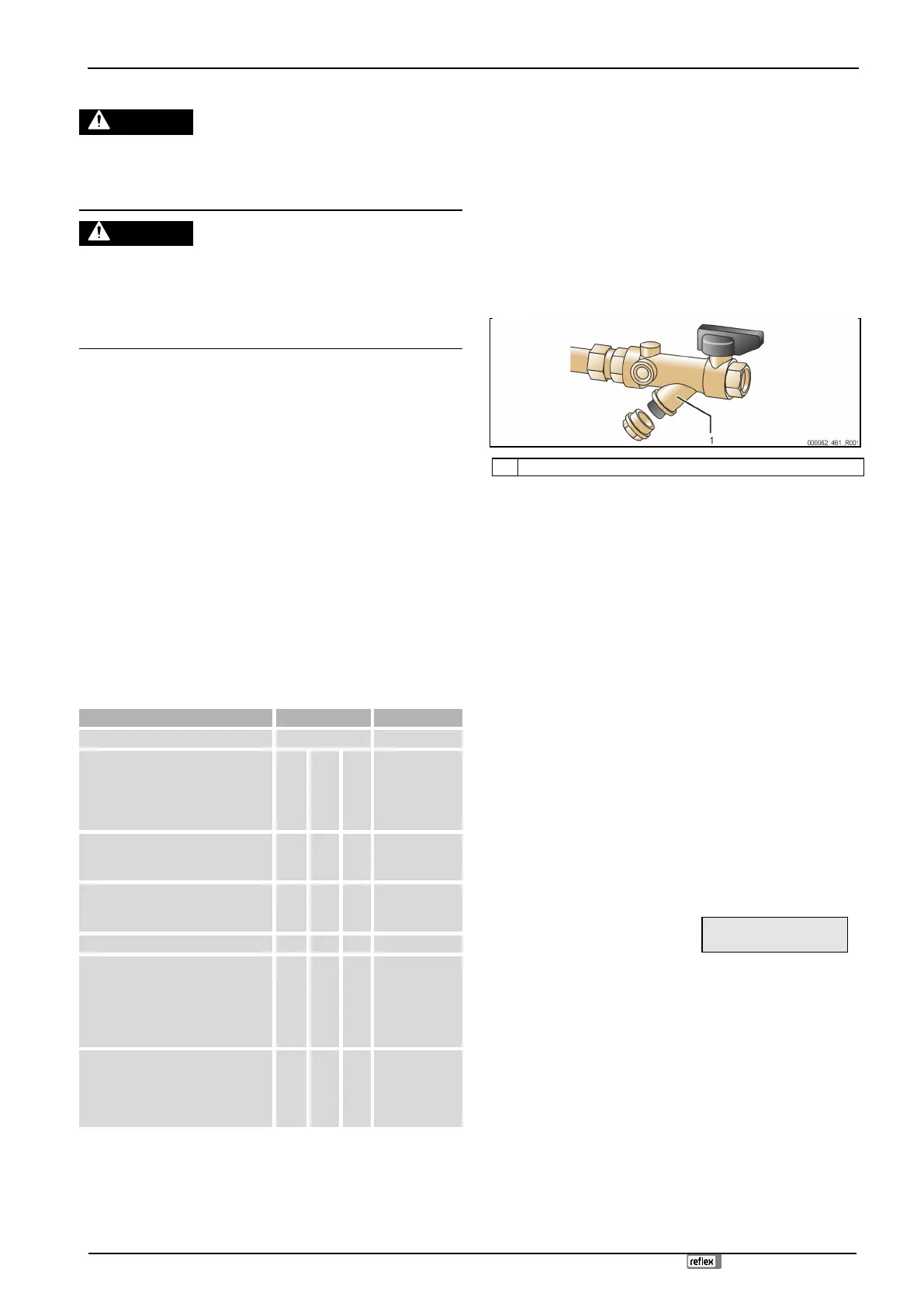
2. Close the ball valve upstream of the "ST" (1) dirt trap.
3. Slowly unscrew the cap with the dirt trap insert at the dirt trap to release
any residual pressure in the pipeline section.
4. Pull the mesh from the cap and rinse it with clear water. Use a soft brush
for cleaning.
5. Re-insert the mesh into the cap, check the gasket for damage, and screw
the cap back into the housing of the "ST" (1) dirt trap.
6. Open the ball valve upstream of the "ST" (1) dirt trap.
7. Press "Auto" on the controller's operator panel.
– The Servitec is switched on and the "PU" pump is in operation.
Note!
Clean all other installed dirt traps (in the Fillset, for example).
9.3 Inspecting system degassing and make-up degassing
Inspect the "SE" system degassing followed by the "NE" make-up degassing.
Press "Manual" at the controller to switch to manual mode. The Auto LED at the
operator panel flashes to visually indicate that manual mode is active. Manually
activate or deactivate the "SE" system degassing and the "NE" make-up
degassing.
You should run at least ten cycles each in the "SE" and the "NE" modes. The gas
must be eliminated before the next cycle starts. Subsequently, check the
following conditions:
• With cold water, the "PI" vacuum gauge must eventually show a value of
approx. -1 bar.
• The "Insufficient water" message must not be displayed at the controller.
After the inspection is completed, reset the device to Automatic mode.
• "Next" and "Back" buttons
– Selecting "NE" or "SE".
• "Auto" button
– Return to Automatic mode.
* Flashing mode "NE▼"
or "SE▲" is activated
 Loading...