11.15
Date Code 20080213 Instruction Manual SEL-351A Relay
Front-Panel Interface (Only on Models With LCD)
Rotating Default Display
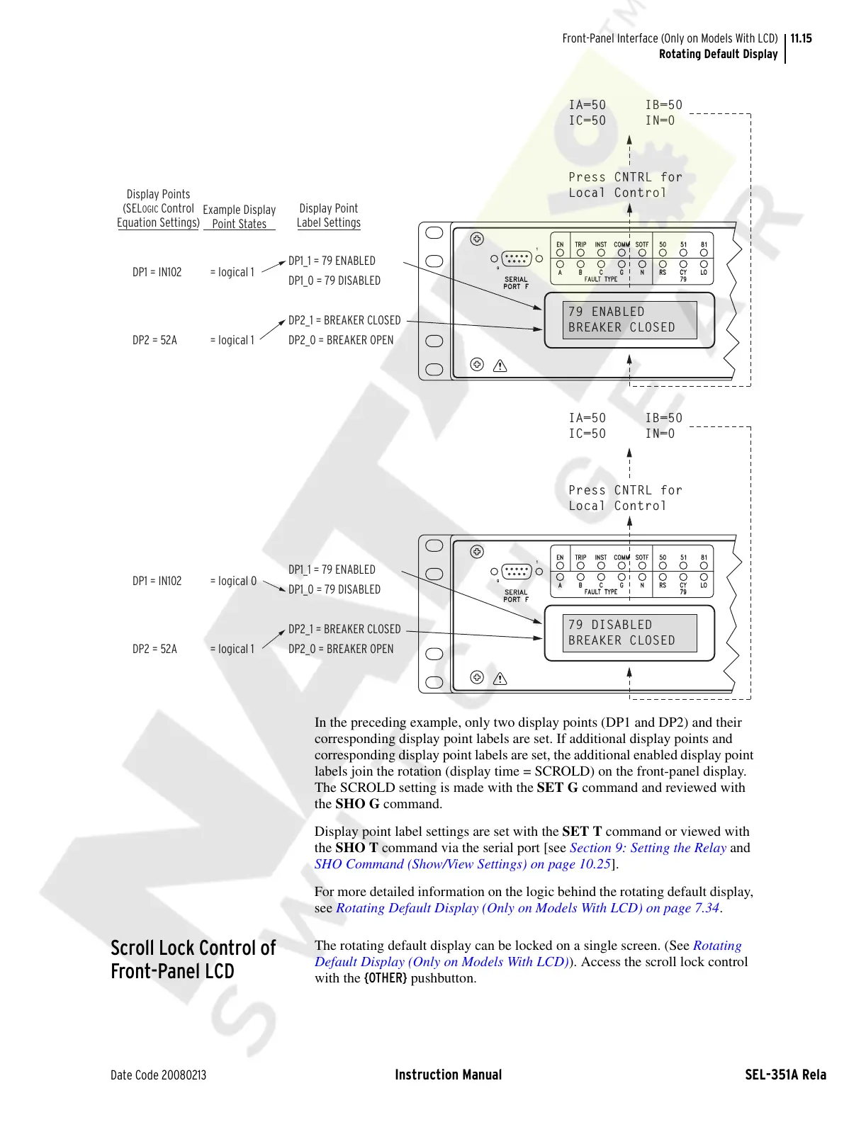
In the preceding example, only two display points (DP1 and DP2) and their
corresponding display point labels are set. If additional display points and
corresponding display point labels are set, the additional enabled display point
labels join the rotation (display time = SCROLD) on the front-panel display.
The SCROLD setting is made with the SET G command and reviewed with
the SHO G command.
Display point label settings are set with the SET T command or viewed with
the SHO T command via the serial port [see Section 9: Setting the Relay and
SHO Command (Show/View Settings) on page 10.25].
For more detailed information on the logic behind the rotating default display,
see Rotating Default Display (Only on Models With LCD) on page 7.34.
Scroll Lock Control of
Front-Panel LCD
The rotating default display can be locked on a single screen. (See Rotating
Default Display (Only on Models With LCD)). Access the scroll lock control
with the {OTHER} pushbutton.
INST
FAULT TYPE
SERIAL
PORT F
9
1
A
B
C
TRIP
EN
50
RS
G
N
COMM
SOTF
79
CY
LO
51
81
Press CNTRL for
Local Control
79 ENABLED
BREAKER CLOSED
IA=50 IB=50
IC=50 IN=0
INST
FAULT TYPE
SERIAL
PORT F
9
1
A
B
C
TRIP
EN
50
RS
G
N
COMM
SOTF
79
CY
LO
51
81
Press CNTRL for
Local Control
79 DISABLED
BREAKER CLOSED
IA=50 IB=50
IC=50 IN=0
Display Points
(SEL
OGIC Control
Equation Settings)
Example Display
Point States
Display Point
Label Settings
DP1 = IN102 = logical 1
DP1_1 = 79 ENABLED
DP1_0 = 79 DISABLED
DP2_1 = BREAKER CLOSED
DP2_0 = BREAKER OPEN
DP2 = 52A = logical 1
DP1 = IN102 = logical 0
DP1_1 = 79 ENABLED
DP1_0 = 79 DISABLED
DP2_1 = BREAKER CLOSED
DP2_0 = BREAKER OPEN
DP2 = 52A = logical 1
Courtesy of NationalSwitchgear.com
 Loading...