A.15
Date Code 20080213 Instruction Manual SEL-351A Relay
Firmware and Manual Versions
Instruction Manual
Section 5
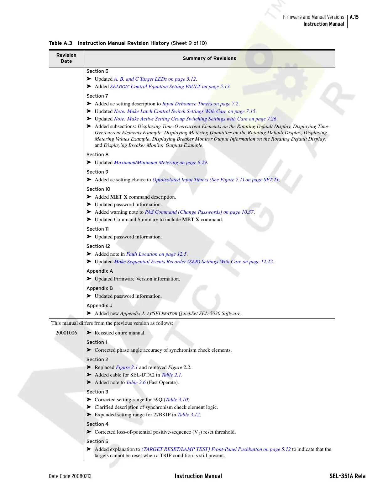
➤ Updated A, B, and C Target LEDs on page 5.12.
➤ Added SELOGIC Control Equation Setting FAULT on page 5.13.
Section 7
➤ Added ac setting description to Input Debounce Timers on page 7.2.
➤ Updated Note: Make Latch Control Switch Settings With Care on page 7.15.
➤ Updated Note: Make Active Setting Group Switching Settings with Care on page 7.26.
➤ Added subsections: Displaying Time-Overcurrent Elements on the Rotating Default Display, Displaying Time-
Overcurrent Elements Example, Displaying Metering Quantities on the Rotating Default Display, Displaying
Metering Values Example, Displaying Breaker Monitor Output Information on the Rotating Default Display,
and Displaying Breaker Monitor Outputs Example.
Section 8
➤ Updated Maximum/Minimum Metering on page 8.29.
Section 9
➤ Added ac setting choice to Optoisolated Input Timers (See Figure 7.1) on page SET.21.
Section 10
➤ Added MET X command description.
➤ Updated password information.
➤ Added warning note to PAS Command (Change Passwords) on page 10.37.
➤ Updated Command Summary to include MET X command.
Section 11
➤ Updated password information.
Section 12
➤ Added note in Fault Location on page 12.5.
➤ Updated Make Sequential Events Recorder (SER) Settings With Care on page 12.22.
Appendix A
➤ Updated Firmware Version information.
Appendix B
➤ Updated password information.
Appendix J
➤ Added new Appendix J: ACSELERATOR QuickSet SEL-5030 Software.
This manual differs from the previous version as follows:
20001006
➤ Reissued entire manual.
Section 1
➤ Corrected phase angle accuracy of synchronism check elements.
Section 2
➤ Replaced Figure 2.1 and removed Figure 2.2.
➤ Added cable for SEL-DTA2 in Tab le 2 .1.
➤ Added note to Tabl e 2.6 (Fast Operate).
Section 3
➤ Corrected setting range for 59Q (Table 3.10).
➤ Clarified description of synchronism check element logic.
➤ Expanded setting range for 27B81P in Tab le 3.12.
Section 4
➤ Corrected loss-of-potential positive-sequence (V
1
) reset threshold.
Section 5
➤ Added explanation to {TARGET RESET/LAMP TEST} Front-Panel Pushbutton on page 5.12 to indicate that the
targets cannot be reset when a TRIP condition is still present.
Table A.3 Instruction Manual Revision History (Sheet 9 of 10)
Revision
Date
Summary of Revisions
Courtesy of NationalSwitchgear.com