Analog input and output parameter group 02
PARAMETER DESCRIPTION 103
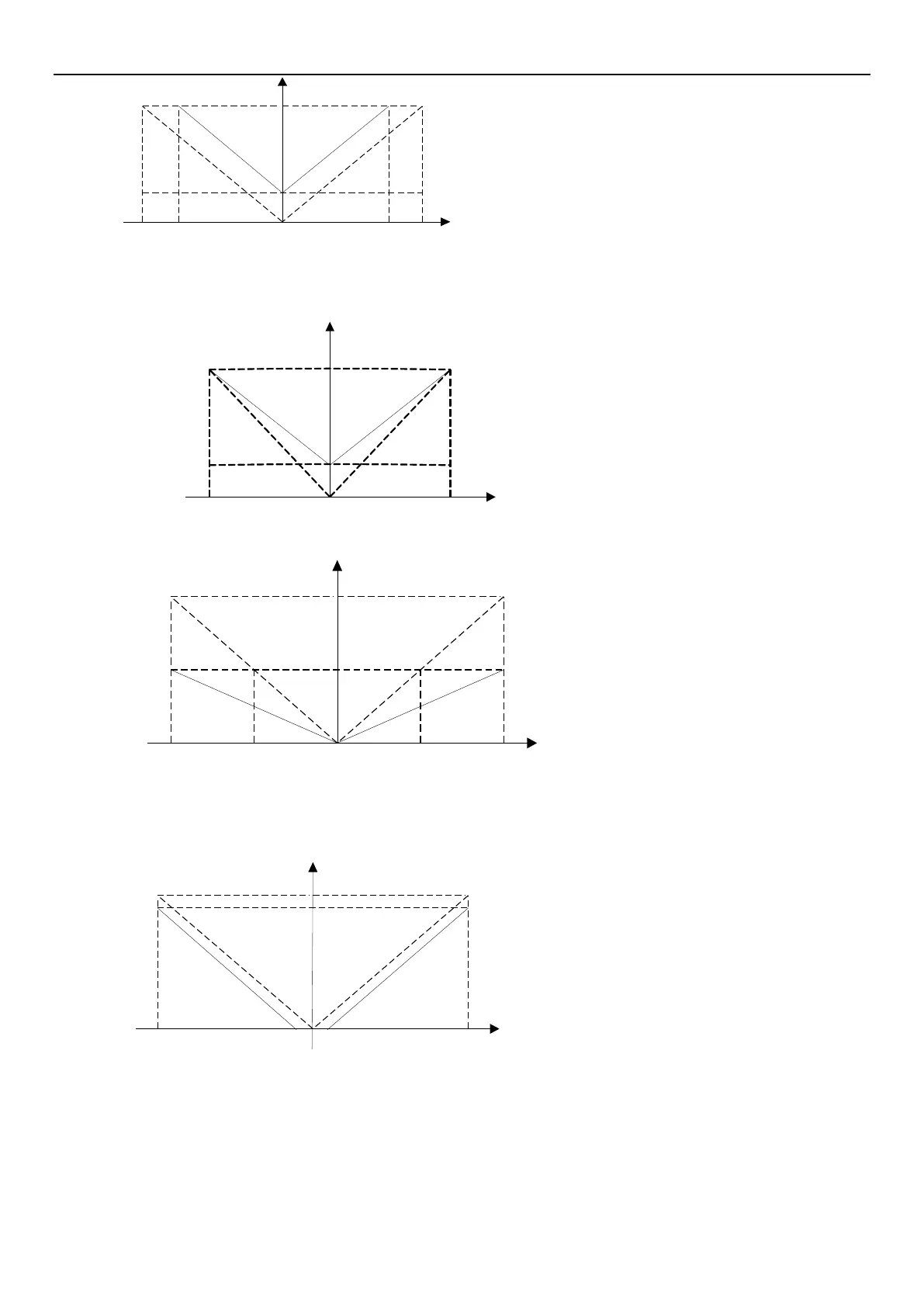
60Hz
02-09(P.38=60Hz Max operation frequency
02-12(P.192=0V, 02-13(P.193=8.33V The minimum/maximum
input positive voltage of terminal 2-5
02-14(P.194=16.7%, 02-15(P.195=100% The setting
corresponding to the minimum/maximum positive voltage of terminal 2-5
02-18(P.510=16.7%, 02-19(P.511=100% The setting corresponding
to the minimum/maximum negative voltage of terminal 2-5
02-16(P.512=0V, 02-17(P.513=8.33V The minimum/maximum
input negative voltage of terminal 2-5
02-14(P.194 = 02-18(P.510 = 10Hz / 60Hz * 100
02-13(P.193= 02-19(P.511= 10V * (100.0 02-14(P.194) /
100
10V
-10V
-8.33V 8.33V
10Hz
0V
Example 4: This example is also frequently used by the industry. The comprehensive usage for all domain of the
potentiometer setup elevates the flexibility.
02-09(P.38=60Hz Max operation frequency
02-12P.192=0V,02-13 P.193)=10V The
minimum/maximum input positive voltage of terminal 2-5
02-14(P.194=16.7%, 02-15(P.195)=100% The setting
corresponding to the minimum/maximum positive voltage of
terminal 2-5
02-18(P.510)=16.7%, 02-19(P.511)=100% The setting
corresponding to the minimum/maximum negative voltage of
terminal 2-5
02-16(P.512=0V,02-17 P.513=10V The
minimum/maximum input negative voltage of terminal 2-5
02-11(P.139) = 0% The bias rate of 2-5 voltage signal
02-14P.1940 =02-15( P.510) = 10Hz / 60Hz * 100
Example 5: This example uses 0~5V to give frequency command.
60Hz
02-09P.38=60Hz Max operation frequency
02-12P.1920=0V, 02-13(P.193)=5V The
minimum/maximum input positive voltage of terminal 2-5
02-14(P.194)=0%, 02-15(P.195)=50% The setting
corresponding to the minimum/maximum positive voltage
of terminal 2-5
02-18(P.510=0%, 02-19P.511=50% The setting
corresponding to the minimum/maximum negative voltage
of terminal 2-5
02-16(P.512=0V,02-17(P.513)=5V The
minimum/maximum input negative voltage of terminal 2-5
02-11(P.139) = 0% The bias rate of 2-5 voltage signal
5V
-5V
30Hz
0V 2.5V-2.5V
Example 6: This example is used to avoid signal below 1V given to inverter as running frequency in harsh
environment, which can greatly avoid the interference of noise.
60Hz
02-09P.380=60Hz Max operation frequency
02-12(P.192)=1V, 02-13(P.193=10V The minimum/maximum input
positive voltage of terminal 2-5
02-14P.194=0%,02-15 P.1950=90% The setting corresponding
to the minimum/maximum positive voltage of terminal 2-5
02-18(P.510=0%,02-19 P.511=90% The setting corresponding
to the minimum/maximum negative voltage of terminal 2-5
02-16(P.512)=1V, 02-17(P.513)=10V The minimum/maximum input
negative voltage of terminal 2-5
02-11(P.139) = 0% The bias rate of 2-5 voltage signal
02-15(P.195) = 02-19(P.511) = 100.0 (1V / 10V) * 100
10V
-10V
54Hz
1V-1V
Example 7: This example is an extension of Example 6. This kind of application is open, user can apply flexibly.
 Loading...


