Arrangement of control terminal
INVERTER INTRODUCTION 40
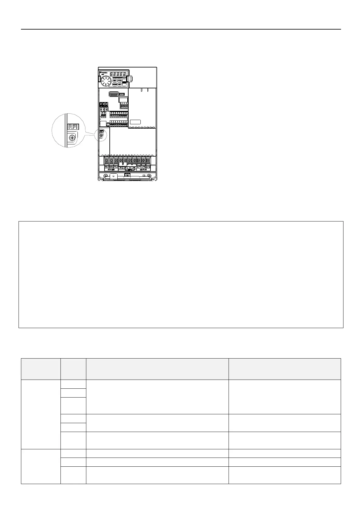
Frame C/D
*1. Frame C:SE3-043-5.5~11K、SE3-023-5.5~7.5K
*2. Frame D:SE3-043-15~22K、SE3-023-11~15K
Frame C/D
RFI filter ON: screw is fastened (default status)
RFI filter OFF: screw is loosened
Note: 1. When the main power supply is switched on, DO NOT switch the status of the RFI filter. Confirm that the main
power supply has been switched off before switching status of the RFI filter.
2. Electrical conductivity of the capacitor will be cut off by switching off the RFI filter. Moreover, the
electromagnetic capacitance of the inverter will be reduced by switching off the RFI filter.
3. When one grounded power system is taken as the main power supply, DO NOT switch on the RFI filter. To
prevent machine from damage, the RFI filter shall be cut off if the inverter is installed on an ungrounded power
system, a high resistance-grounded (over 30 ohms) power system, or a corner grounded TN system.
4. DO NOT cut off the RFI filter during the high-voltage test.
5. When the RFI filter is ON, it can effectively suppress electromagnetic interference, but it also increases
leakage current.
3.7.5 Control circuit
Control terminal name
These are multi-function control terminals, which can be switched
between SINK/SOURCE mode.
Input impedance: 4.7kΩ
Action current: 5mA(24VDC)
Voltage range: 10~28VDC
Maximum frequency: 1kHz
These are multi-function control terminals, which can be switched
between SINK/SOURCE mode.
This is a multi-function control terminal which can be switched
between SINK/SOURCE mode. Compatible HDI function
Maximum frequency: 100kHz
When apply current the input impedance is 235Ω.
When apply voltage the input impedance is 24kΩ.
 Loading...


