Tension control parameter group 14
PARAMETER DESCRIPTION 263
shaft(14-14
(P.612)
).The default radius when releasing is the maximum winding radius(14-13
(P.611)
).
Parameter 14-19
(P.617)
is for setting the winding radius filtering coefficiency.This parameter is used to avoid fast
change of winding radius calculation (or input) result.
Parameter 14-20
(P.618)
is used for displaying the current winding radius.
Parameter 14-21
(P.619)
~14-28
(P.626)
is related to this parameter only when 14-11
(P.610)
=1 or 14-11
(P.610)
=2..
1.
Parameter 14-21
(P.619)
is the pulse per cycle.This setting is mandatory when 14-11
(P.610)
=2.
2.
Parameter 14-22
(P.620)
is cycle per wound layer,mostly used for wire.
3.
When parameter 14-23
(P.621)
=1,material thickness equals to analog input,the maximum value of analog input
corresponds to the value of 14-28
(P.626)
.
4.
When 14-23
(P.621)
=0,the default material thickness is determined by parameter 14-24
(P.622)
.The different
material thickness source can also be selected by the combination of digital input terminals and
14-24
(P.622)
~14-27
(P.625).
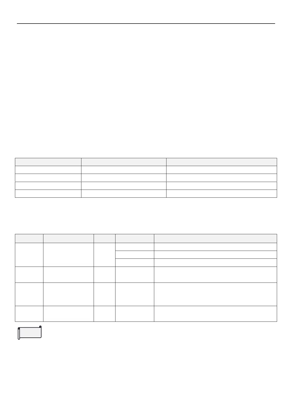
The selections are as follows:
5.15.4 Linear speed input
If the curling radius source selects line speed calculation or tension control mode as the close-loop speed control,
it is required to obtain correct line speed signal.
Linear speed input
source
Analog value or pulse input
Minimum linear speed
calculated by winding
radius
Line speed input
For winding radius source,if linear speed calculation or tension control mode is selectedas closed-loop speed
control,accurate linear speed signal is required.The convenient way fo obtaining linear speed is through analog
output of operation frequency of traction (constant speed) inverter.The operation frequency of traction inverter
corresponds to the linear speed linearly,needing only to set the maximum linear speed (14-30
(P.628)
) to the
corresponding linear speed of the maximum frequency of the operation frequency of the traction inverter.
 Loading...


