PG feedback parameter group 09
PARAMETER DESCRIPTION 202
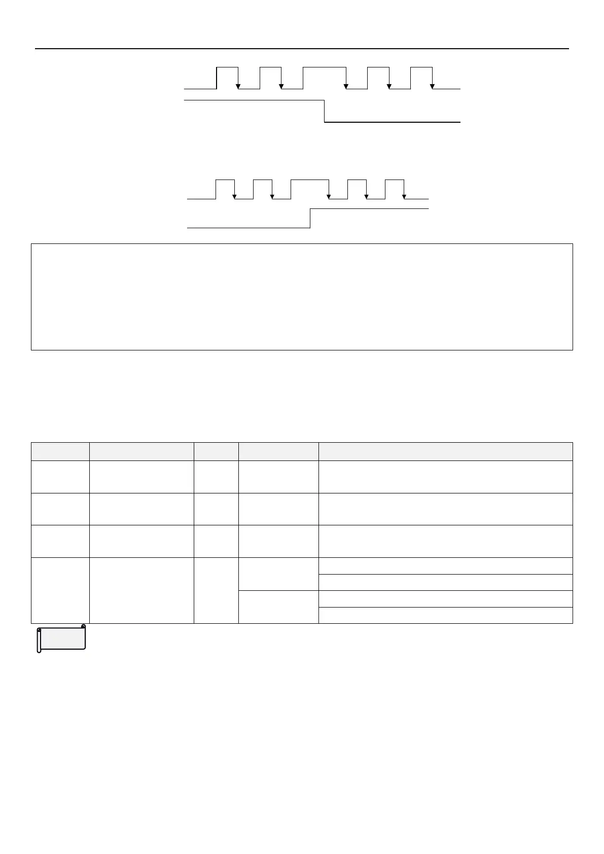
4: Phase A is a pulse train. Phase B is a direction sign. L is forward rotation and H is reverse rotation.
Note:1. If closed loop control is selected,but 09-02(P.351)=0,alarm will be displayed and PG1 ends operation。
2. PG ends operation if PG card and encoder is wired incorrectly or encoder cannot operate properly.
3. When 00-21(P.300)=1,execute IM motor VF closed loop control.When 00-21(P.300)=4,execute IM motor
closed loop vector control;When 00-21(P.300)=5,execute PM motor closed loop vector control.
4. When 10-03(P.151)=1,execute zero-speed under closed loop control,execute DC voltage brake under VF
closed loop control.
5.10.3 PG error detection
The definition of the standard of error detection when PG feedback control.
PG disconnect detection time setting
Overspeed detection
frequency
Motor oversped detection frequency threshold setting
Motor overspeed detection time setting
Encoder signal
detection setting
0:PG302L hardware disconnect detection invalid
1:PG302L hardware disconnect detection valid
0:A1/B1 phase sequence detection invalid
1:A1/B1 phase sequence detection valid
PG abnormality detection
When executing PG feedback control,if detected frequency is 0,and over the set time of 09-03(P.352),it should be
determined as error of PG card`s feed back signal.Inverter will display alarm PG2 and end operation.If PG signal
error(zero speed)detection time 09-03(P.352) is 0,then no PG card feedback signal error function,i.e.,no alarm
PG2.
When executing PG feedback control,if different between detected frequency and output frequency is over
09-04(P.353),and over the time set of 09-05(P.354),the speed deviation should be determined as too fast. Inverter
will display alarm PG3 and end operation.If PG overspeed detection time 09-05(P.354) is set to 0,then no alarm
PG3 function.
 Loading...


