Digital input/ output parameter group03
PARAMETER DESCRIPTION 123
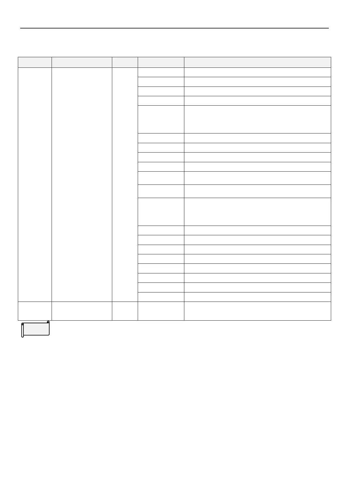
5.4.2 Digital output terminals function selection
Detect information generated and send digital signal output during inverter operation.
RUN(Output when inverter running)
SU(Output when reach target frequency)
FU(Output when reach 03-21(P.62) 03-22 (P.63)value )
OMD(When the percentage of the output current is lower
than 03-23 (P.62) and afte (03-24 (P.63))of time, OMD will
output)
PO1(Output when in program operation step)
PO2(Output when in program operation cycle)
PO3(Output when in program operation pause)
BP(Output when use inverter output in function : switch
between inverter and commercial power-supply)
GP(Output when use commercial power-supply in function :
switch between inverter and commercial power-supply)
OMD1(When inverter reach target frequency and the
percentage of the output current is lower than 03-23 (P.62)
and afte (03-24 (P.63))of time, OMD will output a signal)
RY(Output when inverter is powered on and no alarm)
Output when it’s time for maintenance
OL2 (Output when overload 2)
Output when capacitor abnormal
Output when in position control reach position
Output when detect curl in tension control
Output when detect power marker
Terminal A-B-C output
function
Digital output terminals function selection
Terminal SO default value (03-10(P.40)) is 1 which means “SU”. If 03-10(P.40) value is changed, terminal function
will change as shown in table above.
Terminals SO is “open collector output.” Please refer to Section 3.7 and Section 3.7.6..
Terminal A-B-C default value (03-11(P.85)) is 5 which means “ALARM”. If 03-11(P.85) value is changed, terminal
function will change as shown in table above.
 Loading...


