Application parameter group 10
PARAMETER DESCRIPTION 227
5.11.13 VF complete separation
Voltage command given mode, voltage acceleration/deceleration time and voltage deceleration mode in VF
complete separation.
VF separated voltage
source
Given by digital 10-41(P.701).
Given by analog or HDI pulse.
VF separated voltage
digital
VF separated voltage digital
VF separated voltage
Acc time
Time for voltage accelerating from 0 to motor rated voltage.
VFseparated voltage
Dec time
Time for voltage decelerating from motor rated voltage to 0.
VF separated Stop
selection
Frequency/voltage independently decreases to 0.
After the voltage decreases to 0, frequency decreases.
VF complete separation
Parameter 10-40(P.700)~10-44 (P.704)are valid only when 01-12(P.14)=14. VF complete separation is normally used
in induction heating, inverse power supply and torque motor control.
The voltage source for V/F complete separation is set in the same way as the frequency source, it can be set by
digital or external analog terminal or HDI terminal.
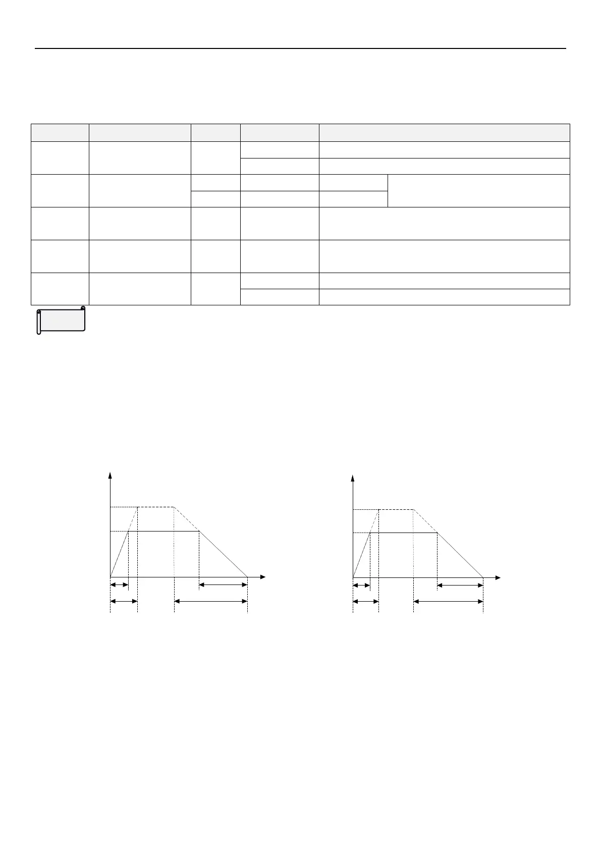
Frequency acceleration time of V/F complete separation indicates the time accelerates from 0 to base frequency
(01-06(P.7)).Frequency deceleration time indicates the time decelerates from base frequency to 0 (01-07(P.8));
voltage acceleration time of VF complete separation indicates the time accelerates from 0 to the rated motor
voltage t1 (10-42(P.702)). Voltage deceleration time of VF complete separation indicates the time decelerates from
the rated motor voltage to 0 t2 (10-43(P.703)).
Time t
Output
frequency
Hz
Base frequency
Set frequency
Actual frequency
acceleration time
Set frequency
acceleration time
Actual frequency
deceleration time
Set frequency
deceleration time
T1
T2
Time t
Output
voltage
V
Rated motor voltage
Target voltage
Actual voltage
acceleration time
Set voltage
acceleration time
Actual voltage
deceleration time
Set voltage
deceleration time
t1
t2
Use 10-41(P.701) to set digital voltage, the setting value cannot exceed motor rated voltage.
When voltage acceleration time is less than frequency acceleration time or voltage deceleration time is more than
frequency deceleration time, voltage stall or current stall may occur during acceleration/ deceleration, which leads
to alarm. So it is suggested that 10-42(P.702) > 01-06(P.7) and 10-43(P.703) < 01-07(P.8).
5.11.14 Regeneration and avoidance function
When inverter load inertia is larger, during deceleration or other process PN voltage will increase due to
regenerative power, and OV alarm will occur. This function can keep PN voltage fixed and prevent PN level from
increasing to OV level by adjusting inverter output frequency and voltage.
 Loading...


