Tension control parameter group 14
PARAMETER DESCRIPTION 266
5.15.7 Pre-drive control
Changing roll during operation can prevent large impact.
Pre-drive torque
increase
Pre-drive torque gain percentage
Pre-drive torque increase delay
Pre-drive control
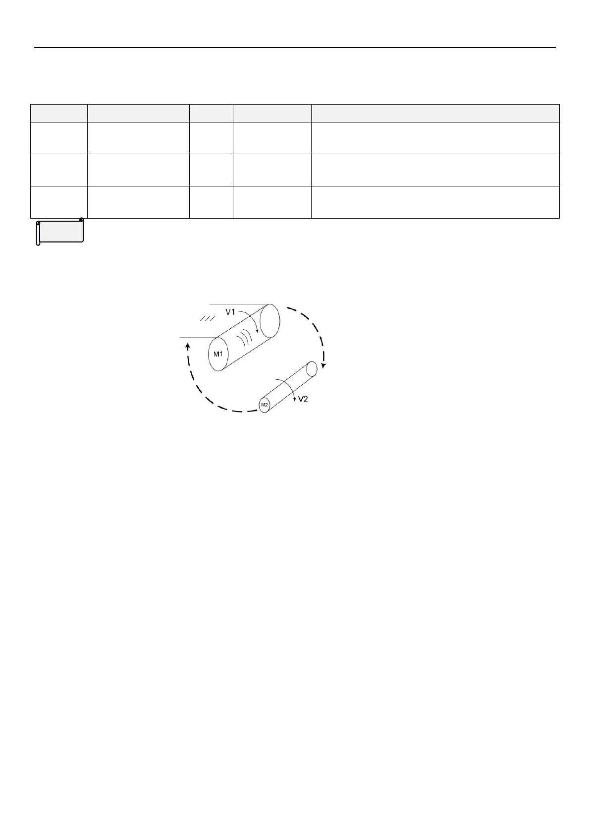
The schematic diagram of auto roll change is as follows,there are two inverters which controls upper roll and lower
roll change.
M1 is called"lower roll to be changed",M2 is called"upper roll to be changed" or "pre-drive roll"
To raise productivity,the winding shaft will generally be switched without turning off the machine.In order to
achieve smooth roll changing and avoid large impact,rotating the winding shaft before hand would be
necessary.The rotation linear speed and the material linear speed is the same.(V1≈V2).This function is called
pre-drive.
Auto roll change control logic
When continuous work,the auto roll change logic is used to achieve a smooth changing process in order to raise
productivity.To achieve auto roll change,external controller is necessary.Motion B、C、D is only active when the
lower roll inverter operates in closed-loop vector control mode(00-21(P.300)=4).
1.
Pre-drive process
When the upper roll inverter receives the pre-drive command,no matter how 14-00
(P.600)
is set,it will operate
according to the matching frequency calculated by the given linear speed and the initial winding radius until
the linear speed of the upper roll is consistent with the system linear speed.When the pre-drive signal
disappears,the control mode will be switched to tension control mode.
2.
Torque memory signal
Before changing roll,the torque memory signal makes the lower roll inverter memorize the current torque for
later process.
 Loading...


