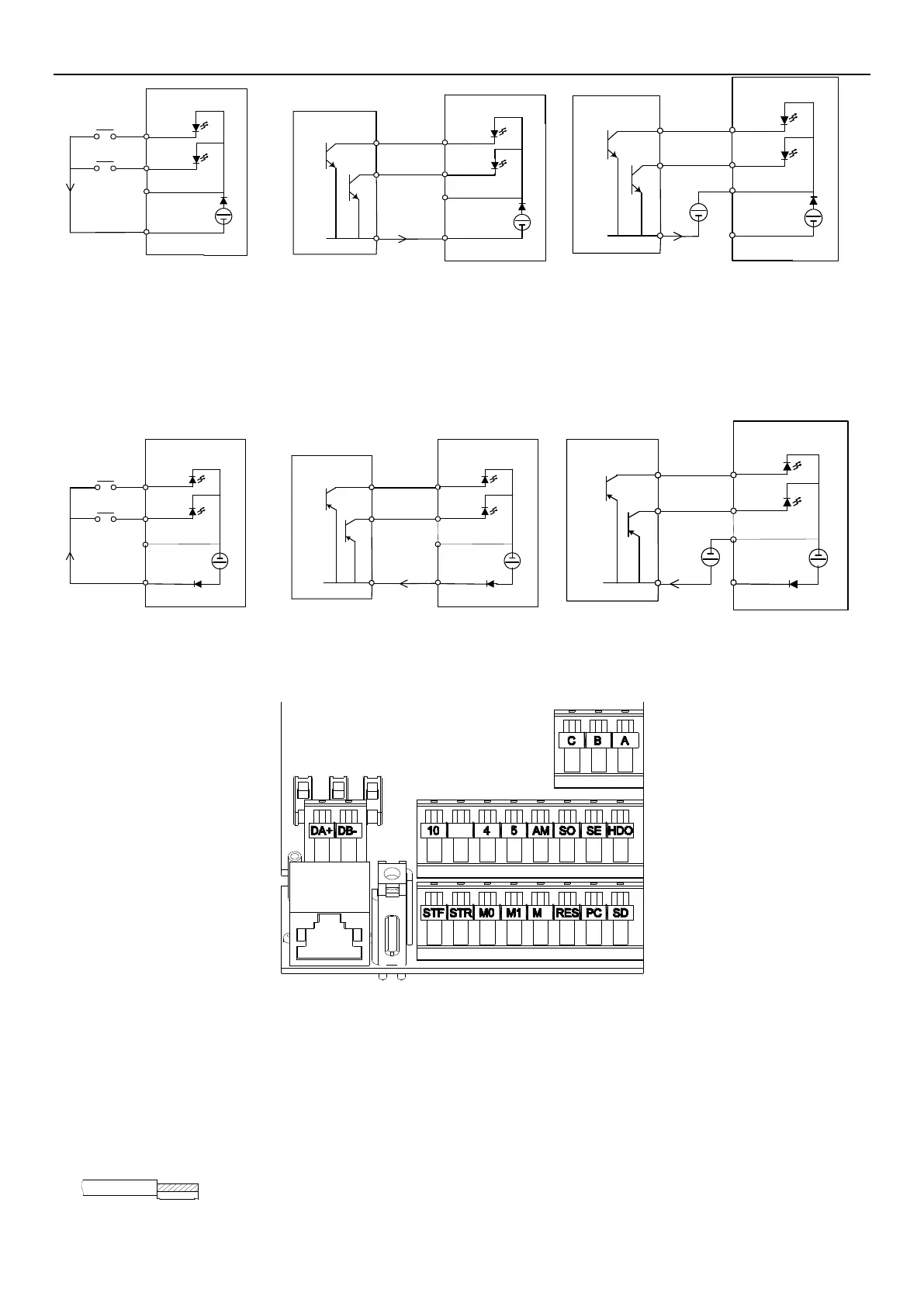
Arrangement of control terminal
INVERTER INTRODUCTION 42
STF
STR
SD
Inverter
Sink Input: the multi-function control
terminal is shorted directly with SD
Sink Input: the multi-function control terminal
is connected directly with open-collector PLC
PLC
I
I
DC
24V
PC
STF
STR
SD
Inverter
DC
24V
PC
Sink Input: the multi-function control terminal is connected
with open-collector PLC and external power supply
PLC
I
STF
STR
SD
Inverter
DC
24V
PC
DC
24V
If "Source Input” mode is selected, when the multi-function digital input terminal is short-circuited to PC or connected to
an external PLC, the function of this terminal is valid. In this mode, the current flows into the corresponding terminal
when it is short. Terminal “PC” is common terminal of the contact input signals. When the output transistor is powered
by an external power supply, use SD terminal as a common terminal to prevent malfunction due to leakage current.
STF
STR
PC
Inverter
Source Input: the multi-function control
terminal is shorted directly with PC
Source Input: the multi-function control terminal
is connected directly with open-emitter PLC
PLC
I
I
DC
24V
SD
STF
STR
PC
Inverter
DC
24V
SD
Source Input: the multi-function control terminal is connected
with open-emitter PLC and external power supply
PLC
I
STF
STR
PC
Inverter
DC
24V
SD
DC
24V
Arrangement of control terminal
Wires connection
For the control circuit wiring, strip off the sheath of a cable, and use it with a blade terminal. For a single wire, strip off
the sheath of the wire and apply directly.
(1) Strip off the sheath for the below length. If the length of the sheath peeled is too long, a short circuit may occur
with neighboring wires. If the length is too short, wires might come off.
Wire the stripped cable after twisting it to prevent it from becoming loose. In addition, do not solder it.
 Loading...


