System parameter group00
PARAMETER DESCRIPTION 62
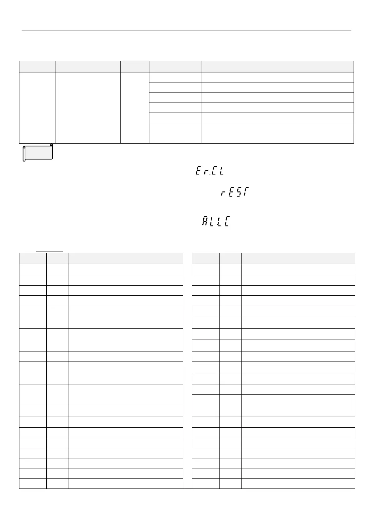
5.1.2 Parameter restoration
Set parameters back to default.
Clear alarm history (P.996=1)
Restore all parameters to default (P.998=1)
Restore some parameters to default 1 (P.999=1)
Restore some parameters to default 2 (P.999=2)
Restore some parameters to default 3 (P.999=3)
Parameter restoration
1: When 00-02(P.996~P.999) is set to 1, screen will flash , the alarm record will be erased after writing,
and 00-02
(P.996~P.999)
is reset to 0.
2: When 00-02(P.996~P.999) is set to 1, screen will flash and inverter will be reset, then
00-02
(P.996~P.999)
is reset to 0. After resetting the inverter, the accumulated values in “electronic thermal relay”
and “IGBT module thermal relay” will be set to zero.
3: When 00-02(P.996~P.999) is set to 3, screen will flash , all the parameters will be restored to the
default values except the parameters in table 1 below. After parameters are restored, 00-02
(P.996~P.999)
is reset
to 0.
Exception
The parameters in table 1 below will not be restored to the default values:
50Hz/60Hz switch selection
Acceleration/deceleration time increments
Monitor inverter digital input terminal state
Monitor inverter and expanded digital
output terminal state
Monitor expanded digital input terminal
state
E1 alarm output frequency
Total inverter operation time (minutes)
E1 alarm the temperature rising
accumulation rate
Total inverter operation time (minutes)
Total inverter power on time (minutes)
Total inverter power on time (days)
E1 alarm the time of the inverter has run
Output power(low 16 position)
E1 alarm the inverter operation status code
Output power(high 16 position)
E1 alarm (minutes/seconds)
E2 alarm output frequency
 Loading...


