Digital input/ output parameter group03
PARAMETER DESCRIPTION 129
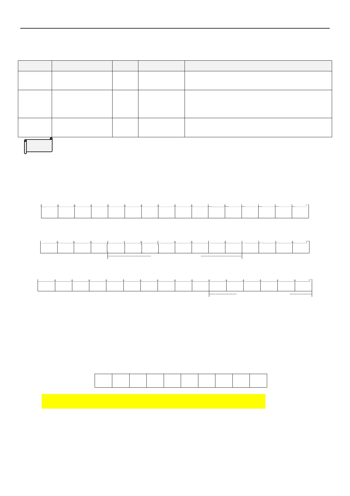
5.4.12 Digital input / output terminal monitor
Used to monitor the status of digital input / output terminal.
Monitor inverter input
terminal state
Monitor inverter and
expanded output
terminal state
Monitor expanded
input terminal state
Digital input / output terminal state
For input terminal: 1 means signal is given, 0 means no signal.
For output terminal: 1 means signal is outputting, 0 means no output.
b0
STFSTRM0M1M2RES
0
00
0
Each bit corresponded input terminal of 03-59(P.585):
b1b2b3
b5
b6b7b8 b4b9
000000
b10b11b12b13b14b15
Each bit corresponded output terminal of 03-60(P.586):
SO0 ABC
0
A10
A11
A12
A13A14
A15
A16A17
expanded digital
output
b0b1b2b3b5b6b7b8 b4b9
0000
b10b11b12b13b14b15
M10
M11M12
M13
M14
M15
0
00
0
0
0
expanded digital
input
b0b1b2b3b6b7b8 b4b9
0000
b10b11b12b13b14b15 b5
Each bit corresponded input terminal of 03-61(P.587)
Example:
Input terminal:
Set 03-00(P.83) = 0(STF), forward rotation signal; 03-03(P.80) = 5(M0), Analog terminal 4-5 priority, other
terminals are default value. After terminal STF and M0 close, inverter operates in forward rotation according to the
frequency given by 4-5. Each bit in 03-59(P.585) is as follows, indicating the operation of STF and M0.
b0
101000
0
00
0
b1b2b3
b5
b6b7b8 b4b9
bit
So 03-59(P.585) = 0×2
9
+ 0×2
8
+ 0×2
7
+ 0×2
6
+ 0×2
5
+ 0×2
4
+ 0×2
3
+ 1×2
2
+ 0×2
1
+ 1×2
0
= 5
Output terminal:
03-42(P.568) (A10), RUN signal detected; 03-49(P.575) (A17) is set set to 2(FU output frequency detected), other
terminals are default value. Insert the expansion card; after the inverter operates to the target frequency, the state
of 03-60(P.586) is as follows, indicating the output of A17 and A10.
 Loading...


