Arrangement of control terminal
INVERTER INTRODUCTION 44
Note: 1. Screwdriver, use small slotted screwdriver (the tip thickness: 0.4mm/tip width: 2.5mm).
2. If the screwdriver tip width is too narrow, it may cause terminal damage.
3. Please alignment terminals by pressing down with the slotted screwdriver, head sliding may cause damage
or injury accident inverter.
4. Installation, wire arrangement, dismounting and maintenance can only be done by qualified electrical
professional personnel.
5. Please follow the wire arrangement notice. If installation is not done by above steps, and inverter is
damaged, our company will not undertake any legal responsibility. In case there is any question on the wire
arrangement, please feel free to contact us.
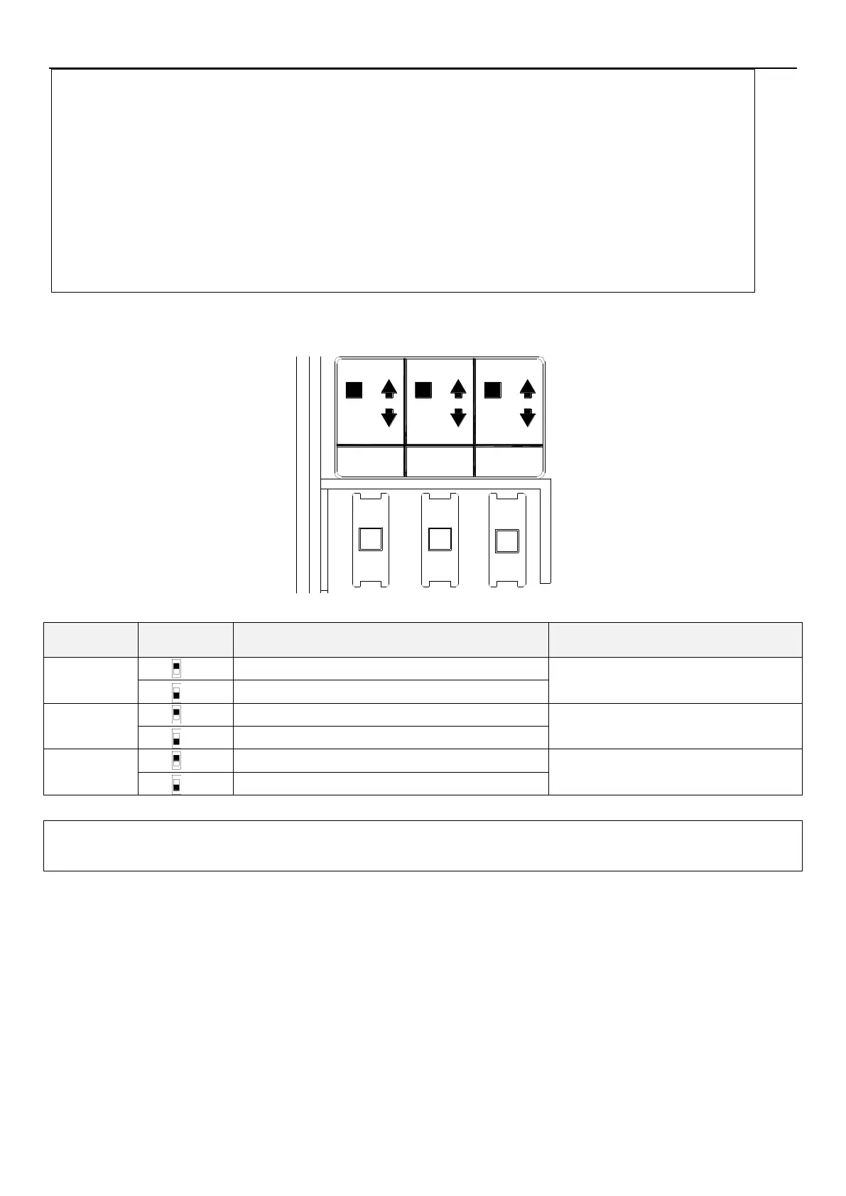
Toggle switch
0-10V
SINK
0-20mASOURCE
SW3
SW1
SW2
4-20mA
0-10V
Please refer to section 3.7.5 control logic
switch.
Output 0~10V voltage from terminal AM
Also requires setting 02-45,
please refer to section 5.3.10.
Output 0~20mA/4~20mA current from terminal AM
Input 4~20mA current signal into terminal 4-5
Also requires setting 02-20,
please refer to section 5.3.6.
Input 0~10V voltage signal into terminal 4-5
Note: 1. The state with “*” is the default state of switch.
2. The parts in black stand for switch handle.
 Loading...


