System parameter group00
PARAMETER DESCRIPTION 70
Carrier frequency
The higher the carrier frequency, the lower the motor acoustic noise, but will result in greater leakage current and
larger noise generated by the inverter.
The higher the carrier frequency, the more energy inverter will consume, and temperature will also be higher.
If mechanical resonance occurred in a system, 00-11
(P.72)
can also be adjusted to lower the vibration.
Note: The setting value of carrier frequency is best to be 8 times larger than the target frequency.
Carrier operation selection
Soft-PWM control is a control method that changes the motor noise from a metallic sound into an inoffensive,
complex tone.
Motor noise modulation control is when the inverter changes its carrier frequency from time to time during
operation, metal noises generated by the motor will not be in a single frequency, so sharp single frequency noises
will be reduced.
This function is only usable under V/F control mode; i.e., it is usable when 00-21(P.300)=0.
5.1.7 Stop operation selection
Select the inverter stop method
button and inverter stop running in PU and
H2(combine mode 2) mode
button and inverter stop running in all
mode.
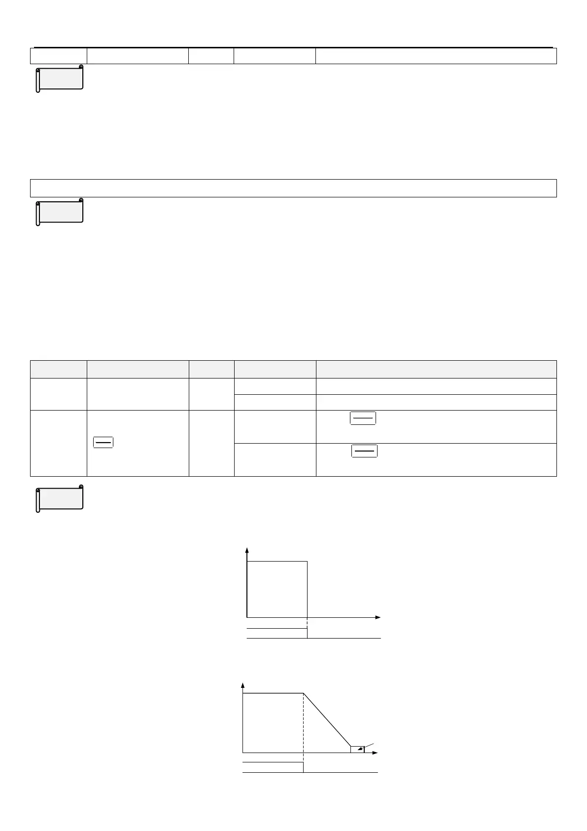
Idling brake / DC brake
Idling brake (00-13(P.71)=“0”)
After receiving stop signal, inverter stops output immediately, and the motor idle freely.
ON OFF
Operation
signal
time
Output frequency
(HZ)
The motor idling breaking
DC braking(00-13(P.71)=“1”)
After receiving stop signal, inverter decelerates according to the acceleration/deceleration curve until it stops
completely.
time
Output frequency (Hz)
ON OFF
Operation
signal
Deceleration time
(the time is set by P.8)
linear
braking
 Loading...


