System parameter group00
PARAMETER DESCRIPTION 73
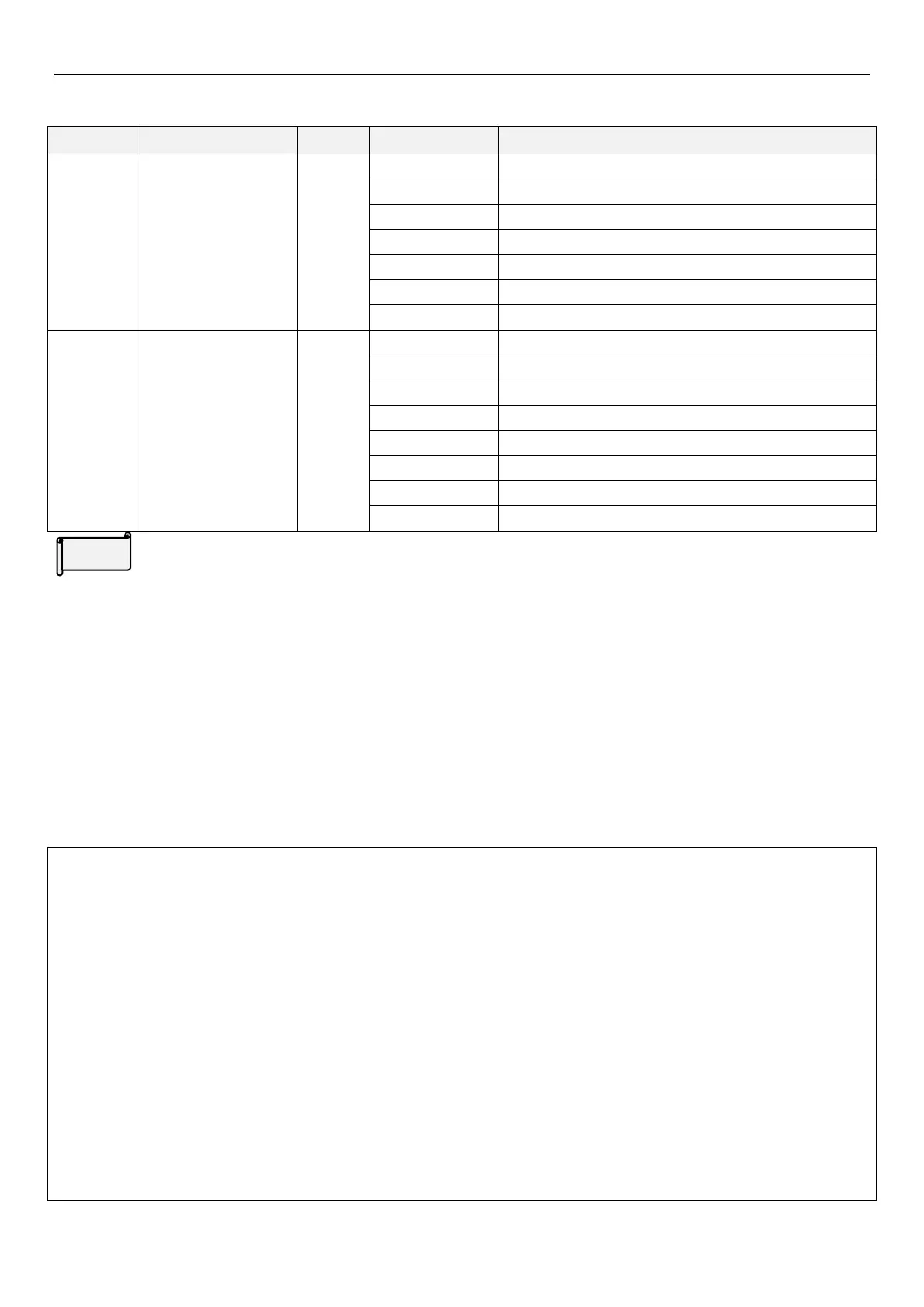
5.1.11 Motor control mode selection
Choose control mode for the AC motor
Motor control mode
selection
Induction motor V/F control
Induction motor closed-loop V/F control (VF + PG)
Induction motor simple vector control
Induction motor sensorless vector control
Induction motor PG vector control
Synchronous motor PG vector control
Synchronous motor vector control without PG
Second motor control
mode selection
Induction motor V/F control
Induction motor close-loop V/F control (VF+PG)
Induction motor simple vector control
Induction motor sensorless vector control
Induction motor PG vector control
Synchronous motor PG vector control
Synchronous motor vector control without PG
Motor control mode
Induction motor V/F control: user can design proportion of V/F as required and can control multiple motors
simultaneously.
Induction motor close-loop V/F control (VF + PG): user can use optional PG card with encoder for closed-loop
speed control.
Induction motor simple vector control: Output voltage is increased to compensate the frequency change when
motor load is increased.
Induction motor sensorless vector control: Auto-tuning the motor to reach optimal control performance.
Induction motor PG vector control: Increases
output
torque and accuracy of speed control.
Synchronous motor PG vector control: Increases output torque and accuracy of speed control.
Synchronous motor without PG vector control: get the optimal control by the auto-tuning of motor parameters.
Note: 1. The motor capacity must be the same level or one level lower than the inverter capacity.
2. Sensorless vector control: Control performance can be enhanced by auto-tuning. Before setting 00-21
(P.300)= 3 or 4, please set the motor parameters first, then do auto-tuning to increase the precision of the
control.
3. When selecting V/F + PG (set 00-21(P.300) = 1) control mode, please be sure to set the right motor pole
number (05-02(P.303)).
4. When 10-03 (P.151) = 1, the motor performs zero-speed operation under closed-loop vector control; motor
performs DC voltage braking under V/F closed-loop control.
5. When 00-22(P.370) ≠ 99999 and RT signal is given, the second motor parameters
05-22(P.332)~05-38(P.394) are valid, please refer to section 5.2.10 for second function parameter.
6. RT mentioned here is the function name of “multi-function digital input terminal”. Please refer to
03-00~03-05(P.80~P.84、P.86), P.86,for the function selection of multi-function digital input terminal; please
refer to section 3.5 for related wiring.
 Loading...


