Protection parameter group06
PARAMETER DESCRIPTION 153
5.7.3 Regenerative brake
When performing frequent start and stop operation, regenerative brake usage rate can be increased by using the
brake resistor or the brake unit.
Regenerative brake
During the period when output frequency of inverter changes from high frequency to low frequency, due to load
inertia, the rotating speed of the motor is higher than the output frequency of inverter at an instant, thus forming the
generator effect. This will cause regenerative voltage between main circuit terminals (+/P)-(-/N), which may result
in damage to inverter. Therefore, a regenerative braking resistor with an appropriate size is installed between main
circuit terminals +/P and PR to absorb the feedback energy.
There is a transistor in inverter and the proportion of conduction time is called “regenerative braking rate”. The
greater the value of regenerative braking rate, the more energy regenerative braking resistor consumes and the
stronger the braking capability.
5.7.4 Decrease carrier protection setting
It selects decrease carrier or decrease rated current protection by setting parameters.
Decrease carrier
protection setting
Fixed carrier frequency, and limit output current according to
carrier value.
Fixed rated current, and limit carrier according to output
current and temperature.
Decrease carrier protection
06-07(P.263)=0, fixed carrier frequency, but the rated current of inverter will be reduced according to set carrier
frequency and corresponding curve, so as to avoid overheating of IGBT module on inverter:
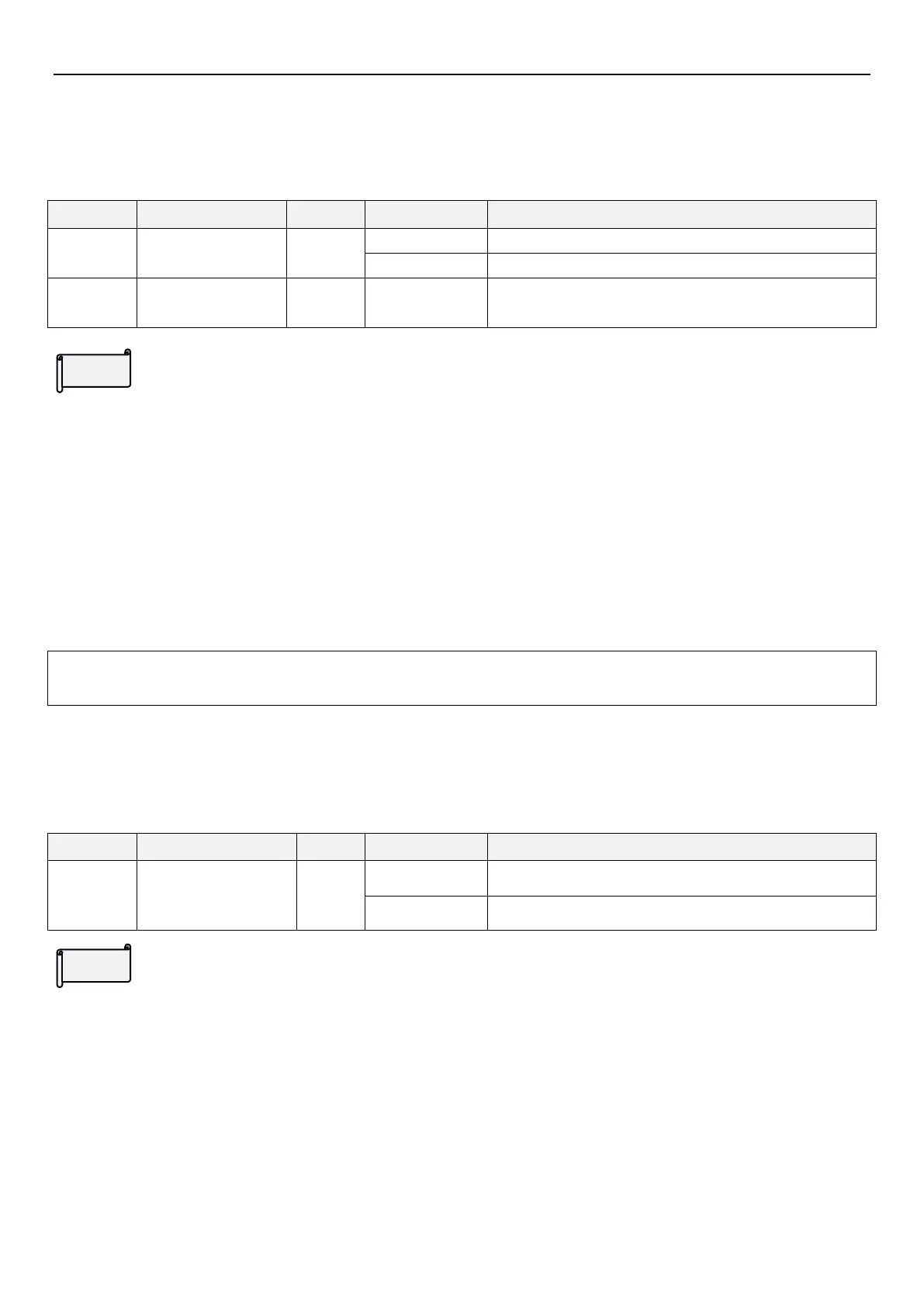
Regenerative brake
selection
Brake duty is fixed at 3%, parameter 06-06(P.70) will be off.
Brake duty is 06-06(P.70) value.
Special regenerative
brake duty
Note: 1. If inverter is used in high-frequency start/stop case, it need a high-power regenerative braking resistor.
2. Please refer to section 3.6.3 for choosing regenerative braking resistor.
 Loading...


