Operation modes of inverter
PRIMARY OPERATION49
When 00-16(P.79)=0, the external mode ( ) is the default mode after inverter is turned on. Use 00-16(P.79)
to switch the operation mode.
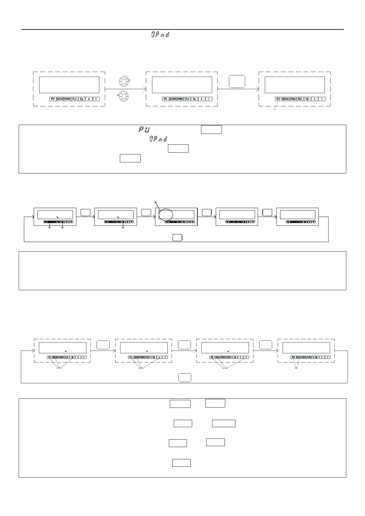
4.2.1 Flow chart for switching operation mode
4.2.2 Flow chart for switching working mode with PU302 keypad
RESET
STOP
FWDREV
SETMODE
L
Cr
E
0
0
0
MODE
light up
0
0
0 -
0
0
MODE
0
0 0
glitter
MODE
D
N
PO H E
L
P
MODE
MODE
light up
light up
Note: 1. Please refer to section 4.2.3 for detailed operation steps under monitoring mode.
2. Please refer to section 4.2.4 for detailed operation steps under frequency setting mode.
3. Please refer to section 4.2.5 for detailed operation steps under parameter setting mode.
4. Please refer to Section 4.2.1 for detailed operation steps under switching operation mode.
4.2.3 Operation flow charts for monitoring mode with PU302 keypad
●Take PU mode for example:
Note: 1. In “PU mode”, keypad screen displays , and the indicator in
will light up.
2. In “external mode”, keypad screen displays ,
3. In “combined mode 1, 2, 3, 4, or 5”, the indicator in
will flash on the keypad screen.
4. In “JOG mode”, the indicator in
will light up.
5. No flow chart when 00-16(P.79) is set to =2, 3, 4, 5, 6, 7 or 8 because the operation mode will not switch
Note: 1. In “monitoring output frequency” mode, indicator in
will light up, and the screen will display current
output frequency.
2. In “monitoring output voltage” mode, indicator in
will light up, and the screen will display
current output voltage.
3. In “monitoring output current” mode, indicator in
will light up, and the screen will display current
output current.
4. When in “browsing alarm record”mode, indicator in
will light up, and the screen will display current alarm code.
5. For alarm codes, please refer to Appendix 2.
SET
E
0
SETSET
0
0
0
0
0
light up
SET
0
0
0 0
light up
light up light up
 Loading...


