PG feedback parameter group 09
PARAMETER DESCRIPTION 189
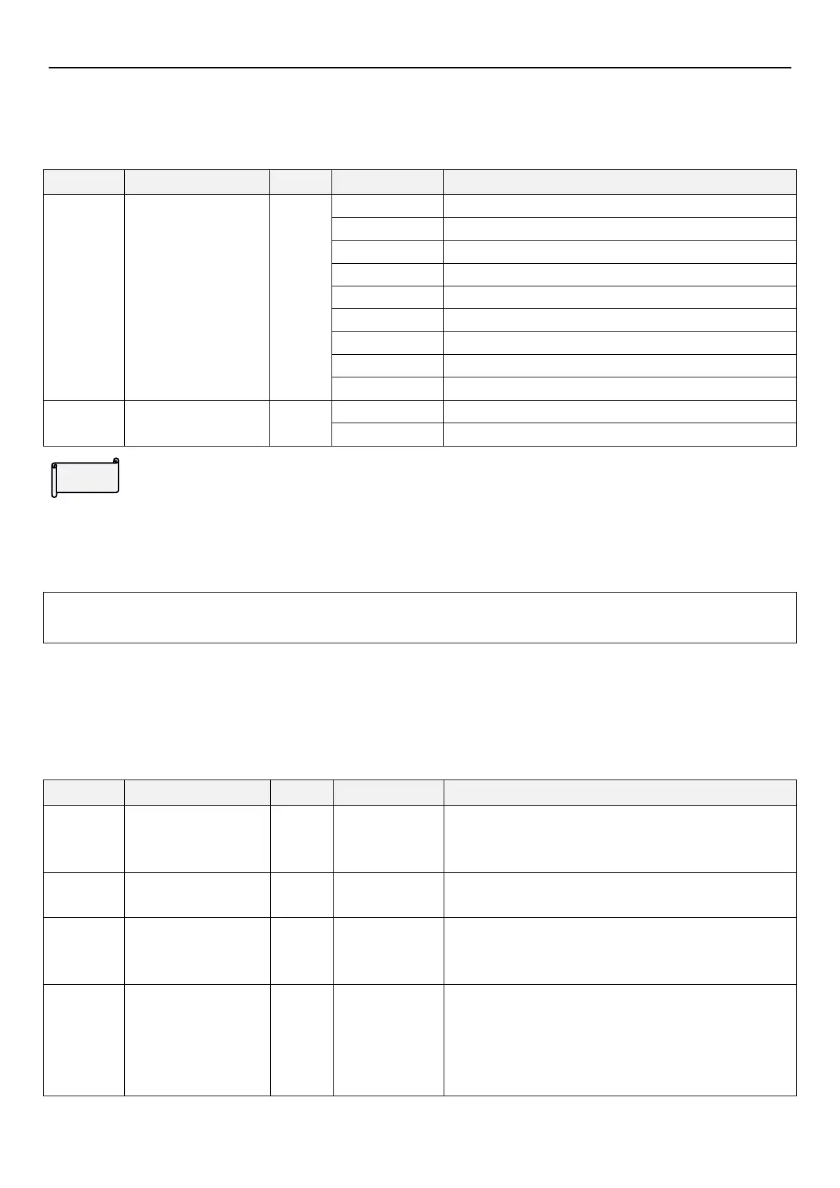
5.9.1 PID function selection
Inverter can control flow, volume or pressure by PID control. By using analog signal or parameter setting as target
source, and with analog signal as feedback source, it forms a closed loop control system.
Parameter 08-03(P.225) as target value.
Terminal 2-5 input as target source
Terminal 4-5 input as target source
Terminal HDI input as target source
Terminal 2-5 input as feedback source
Terminal 4-5 input as feedback source
PID feedback control
method
Negative feedback control.
Positive feedback control.
PID function selection
During PID control, frequency displayed on screen is inverter output frequency
For terminal 2-5 and terminal 4-5 input signal filtering please refer to parameters 02-10
(P.60)
02-22
(P.528)
.
Note: When setting target source and feedback source, please pay attention to 08-00(P.170) and
02-00(P.500)~02-01(P.501) setting, terminal priority : 2-5 > 4-5 .
5.9.2 PID parameter group 1
By setting PID parameters users can realize automatic adjustment of process control.
Feedback signal sampling period.Adjuster computes once
every sampling period. The longer the sampling period, the
slower the response.
When ten-digit of 08-00 (P.170) is set to 0 and single-digit is
not set to 0, the target value is set by 08-03(P.225)
This gain determines the proportion controller’s response on
feedback deviation. The greater the gain, the faster the
response. Gain set too high will cause vibration.
This parameter determines integral controller’s integral time.
When integral gain is too high, integral effect will be too
weak to eliminate steady state deviation. When integral gain
is rather small, the system vibration time will increase, and
too small integral gain will cause system unstable.
 Loading...


