Digital input/ output parameter group03
PARAMETER DESCRIPTION 119
Terminal M0 input
function
Terminal M1 input
function
Terminal M2 input
function
Digital input terminals function selection
At default, 03-03(P.80)=2(RL), 03-04(P.81)=3(RM), 03-05(P.82)=4(RH), 03-00
(P.83)
=0(STF), 03-01(P.84)=1(STR),
03-02(P.86)=30(RES).
Changing 03-01(P.84)~03-03(P.80) settings change the function of the terminals. For example, 03-03(P.80)=2
means that M0 terminal acts as RL. If 03-03(P.80) is set to 8, M0 terminal function will change to RT, which will act
as “second function”. Another example, 03-00
(P.83)
=0 means that STF terminal serves as “inverter runs forward”
function, and if change 03-00
(P.83)
to 6, STF terminal function will change to OH, which will serve as the input
terminal of external thermal relay..
Set value:5 AU(Analog terminal 4-5 high priority)
When this terminal is ON, frequency command source priority will force to 4-5. (If the frequency commands are
given to 4-5, 2-5 at the same time, the priority will become 4-5>2-5 when this terminal is on).
Set value:6 OH(External thermal relay):
Old motors usually come with thermal relay attached to the front of the motor to prevent motor from overheating.
When external thermal relay actuate, inverter will alarm and show “OHT”.
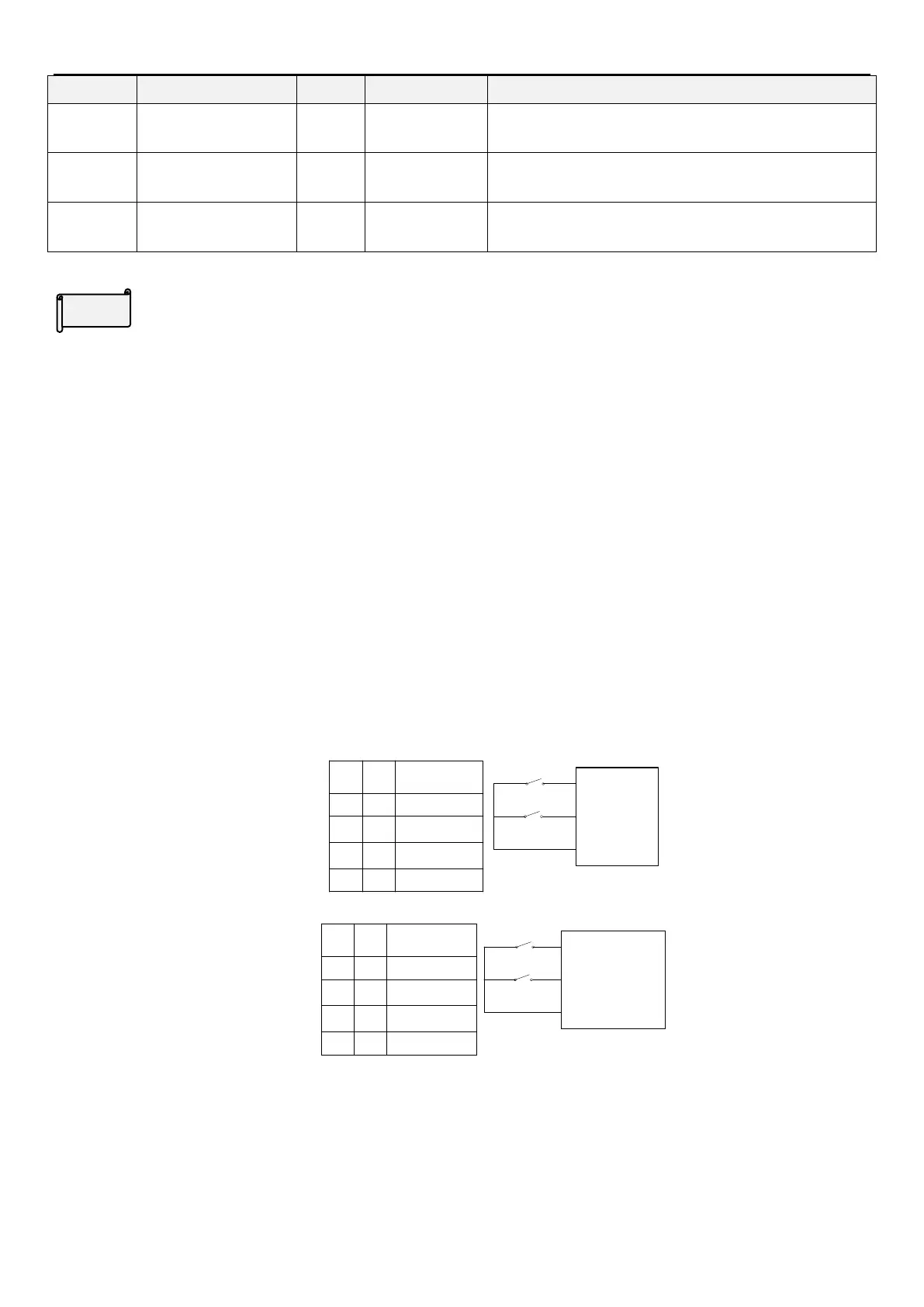
Four different wiring techniques (1 means ON, 0 means Off, and X = 0, 1, 2, 3, 4, 6)..
1) Two-wire control mode 1:
K0
K1
STF(P.8X=0)
STR(P.8X=1)
SD
K0
K1
Operating
Instructions
0
1
0
1
11
0
0
Stop
Run Forward
Run Reverse
Stop
2) Two-wire control mode 2:
K0
K1
RUN(P.8X=28)
STF/STR(P.8X=29)
SD
K0 K1
Operating
Instrnctions
0
1
0
1
11
0
0
Stop
Run Forward
Run Reverse
Stop
3) Three-wire control mode 1 (with seal-in function): K0 is STOP, normal close. When trigger inverter will stop.
K1 is forward and K2 is reverse, normal open. All K0 K1 K2 are edge trigger button.
 Loading...


