Application parameter group 10
PARAMETER DESCRIPTION 223
automatically switch to inverter operation and operate at the frequency of the frequency command. If the inverter
start command (STF/STR) is set to OFF, it will also switch to
inverter operation.
If 10-32(P.250)=99999, 10-31(P.249)≠99999 will be valid at automatic switching operation. After switching from
inverter operation to commercial supply, the inverter start command (STF/STR) will be set to OFF and then switch
to inverter operation, and slow down to stop.
Examples for commercial power supply frequency switchover function:
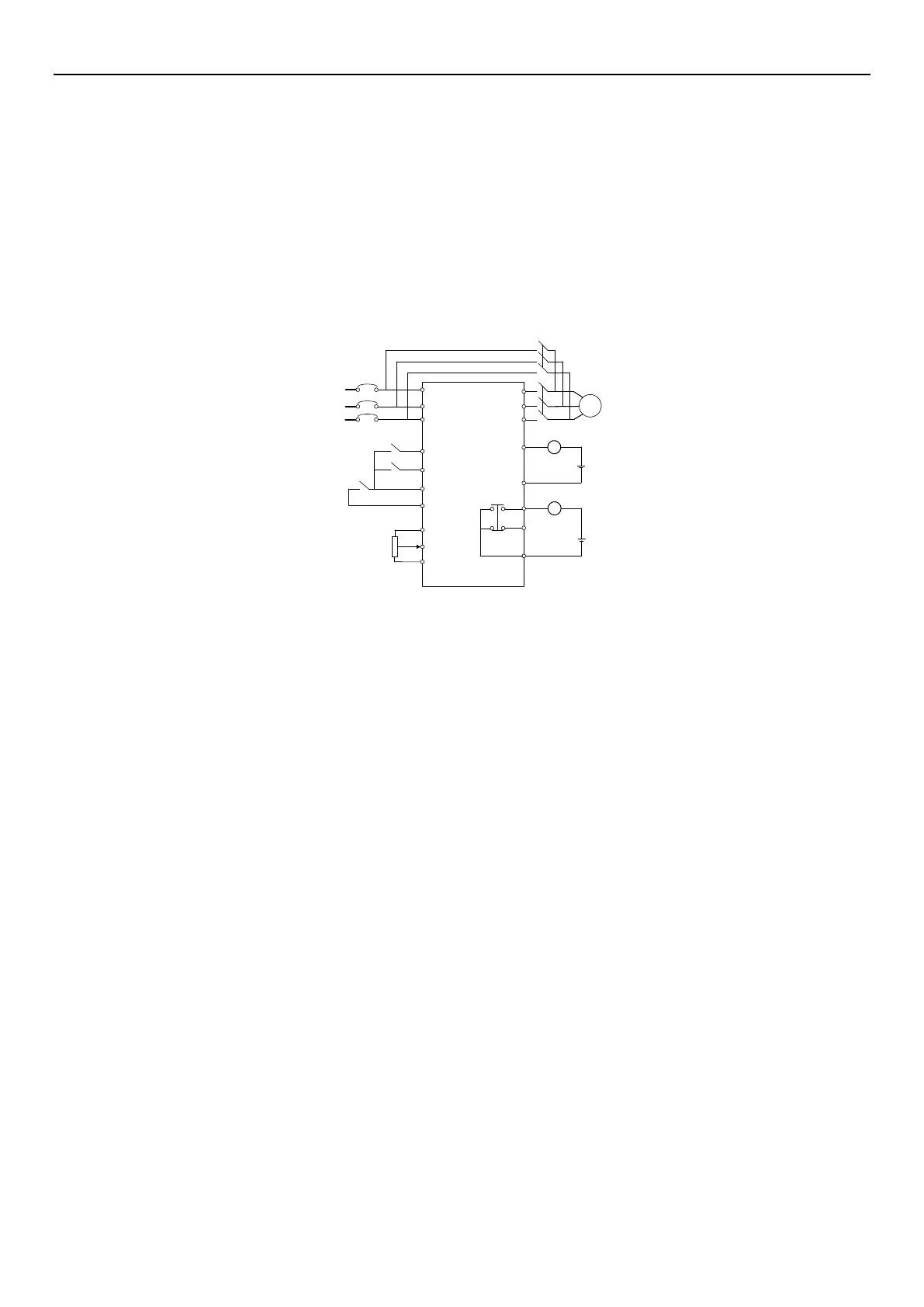
1.
Set 03-03(P.80) = 37, 03-04(P.81) = 38, 03-10
(P.40)
= 10 and 03-11
(P.85)
= 9. The wiring diagram is presented
below:
NFB
R
S
T
M
MC1
MC2
MC1
DC24V
STF
M1
M0
SD
SO
SE
K1
K3
K2
10
5
2
U
V
W
MC2
DC24V
A
B
C
Terminals used are different according to the settings of 03-10(P.40), 03-11(P.85) (output terminal function selection).
If selecting output terminal function 10, connect the relay driving commercial power supply, and if selecting output
terminal function 9, then connect the relay driving frequency conversion. If selecting digital input terminal function
37, choose commercial power supply switching function; and if selecting digital input terminal function 38, choose
the manual commercial power supply switching signal CS.
Warning:
1. MC1 and MC2 must be mechanically interlocked; the running direction of inverter operation and the commercial
power supply operation should be consistent.
2. Use the commercial power operation switchover function under external operation mode.
3. STF/STR is valid when the CS signal is ON.
Here are some typical sequence diagrams for the switchover of the commercial power supply frequency:
1. No action sequence for the automatic switchover sequence (10-31(P.249) = 99999).
 Loading...


