Speed and torque control parameter group11
PARAMETER DESCRIPTION 237
Has nothing to do with run command
Has nothing to do with torque command
direction and motor run direction
11-15(P.404) is torque filter coefficient. When set larger, control will be stable, but response will be worse. When set
too small, response will be quick, but control can be unstable. If don’t know which value to set, adjust the value
appropriately according to the level of unstable and response delay.
When 11-16(P.405)=1, torque is given by analog or pulse input. Maximum value of analog and pulse correspond to
motor rated torque. When 11-16(P.405)=2, torque is given by communication mode. There are two ways to set
torque by communication mode, one is changing 11-12(P.401) value when 11-16(P.405) is set to 0, and another is by
Modbus communication address H100D when 11-16(P.405) is set to 2. When Modbus communication address
H100D is set to -10000~10000, it represents -100%~100% of the motor rated torque.
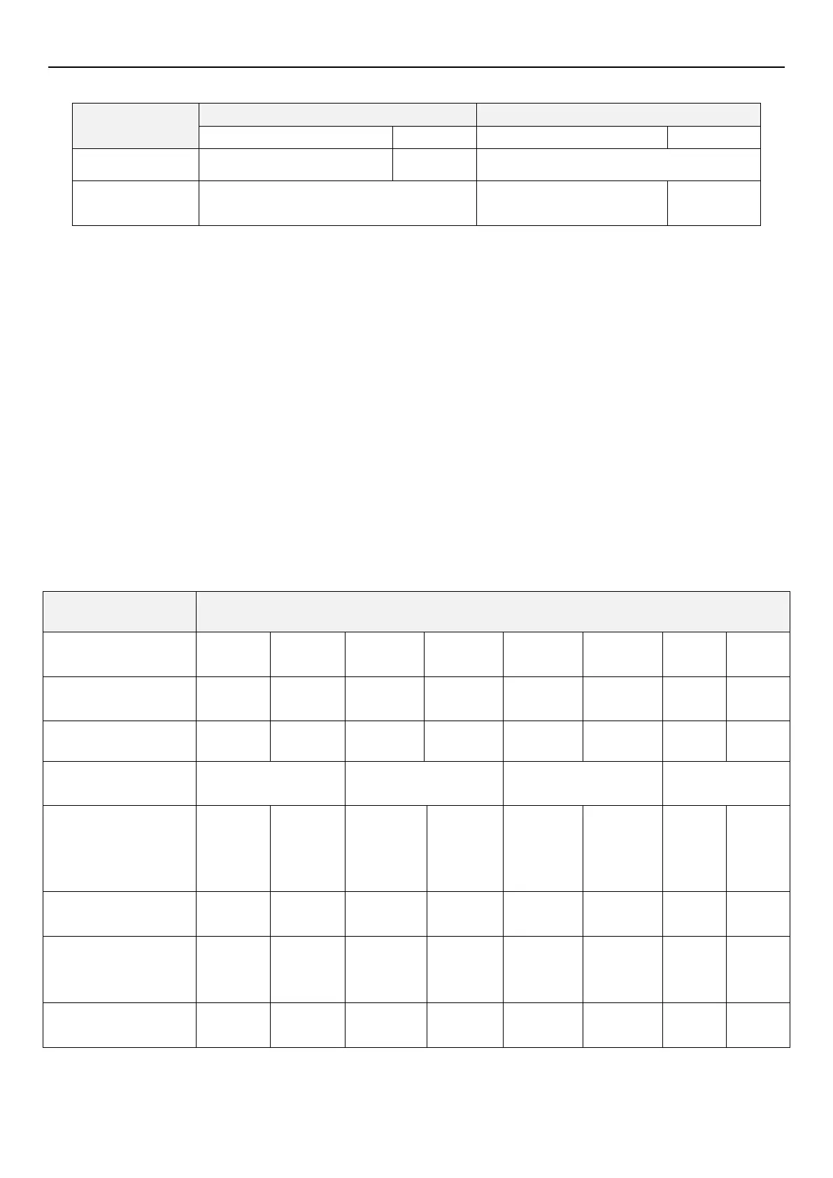
Speed limit and speed limit bias of torque control
When 11-17(P.406)=0,limit speed in torque control according to 11-13(P.402) and 11-14(P.403);When 11-17(P.406)=1,
limit speed in torque control according to frequency source, which is set by 00-16(P.79).
A bias can be added to speed limit using parameter 11-14(P.403) and parameter 11-18(P.407) determines how the
speed limit bias is applied. The following sheet shows the setting relationship, and “frequency” in sheet refers to
frequency command set by frequency source which is set by 00-16(P.79).
Torque reference
direction
Normal operation
direction
Normal speed limit
(11-18=0,11-17=0)
11-13
(P.402)+
11-14
(P.403)
11-13
(P.402)+
11-14
(P.403)
11-13
(P.402)+
11-14
(P.403)
11-13
(P.402)+
11-14
(P.403)
Normal speed limit
(11-18=1,11-17=0)
Normal speed limit
(11-18=0,11-17=1)
Frequency
+ 11-14
(P.403)
Frequency
+ 11-14
(P.403)
Frequency
+ 11-14
(P.403)
Frequency
+ 11-14
(P.403)
Normal speed limit
(11-18=1,11-17=1)
 Loading...


