Stage Description
Logic of the Stage
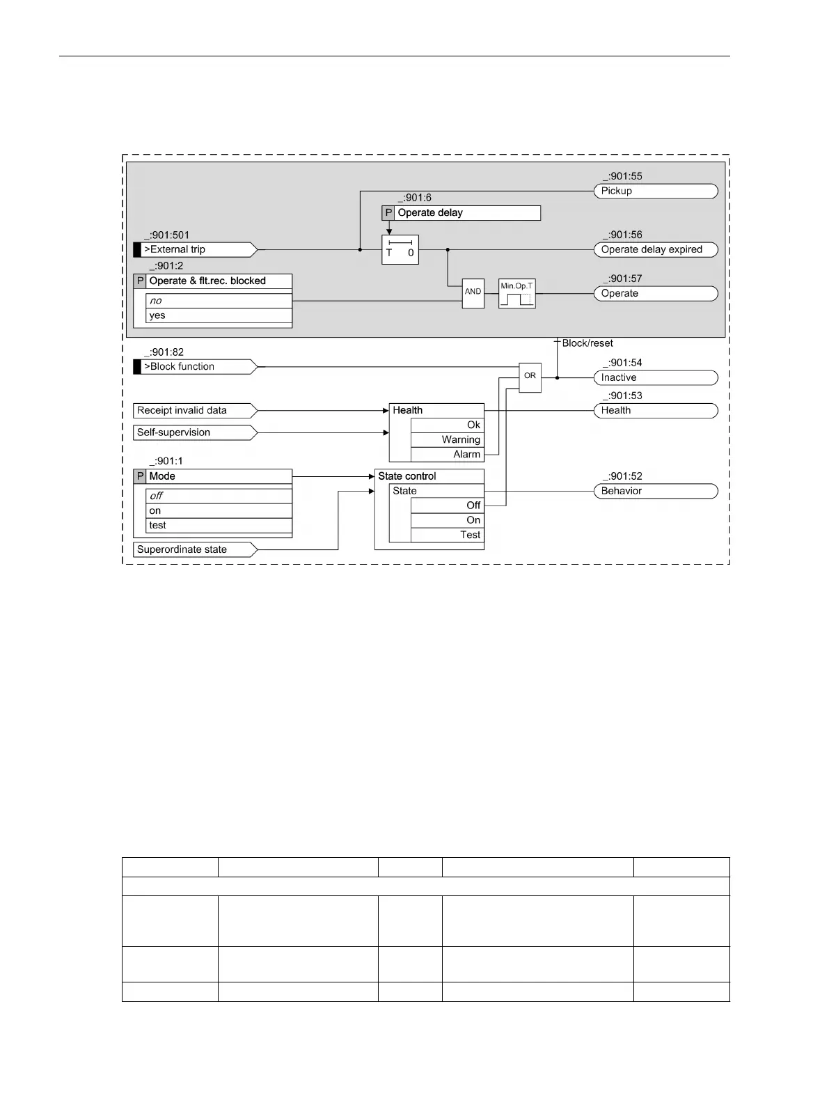
[lotrip3p-070611-01.tif, 1, en_US]
Figure 7-57
Logic Diagram for the External Trip-Initiation Stage
Binary Input Signal >External Trip
The binary input signal >External trip starts the Pickup and the Operate delay.
Blocking the Stage
The stage can be switched to ineffective via a number of signals. If the stage is in the pickup state at the time
of blocking, it will be immediately reset. However, the operate indication remains stopped for the minimum
operating time (_:102) Minimum operate time.
Application and Setting Notes
Settings
Addr.
Parameter C Setting Options Default Setting
Stage 1
_:901:1 Stage 1:Mode
•
off
•
on
•
test
off
_:901:2 Stage 1:Operate & flt.rec.
blocked
•
no
•
yes
no
_:901:6 Stage 1:Operate delay 0.00 s to 60.00 s 0.05 s
7.3.3
7.3.4
7.3.5
Protection and Automation Functions
7.3 External Trip Initiation 3-Pole
596 SIPROTEC 5, High-Voltage Bay Controller, Manual
C53000-G5040-C015-9, Edition 11.2017