RM0440 Rev 4 387/2126
RM0440 Peripherals interconnect matrix
401
Timers (TIMx, HRTIM) can be used to generate an ADC triggering event.
TIMx synchronization is described in: Section 28.3.31: ADC synchronization (TIM1/TIM8).
ADC synchronization is described in: Section 21.4.18: Conversion on external trigger and
trigger polarity (EXTSEL, EXTEN,JEXTSEL, JEXTEN).
Triggering signals
The output (from timer) is on signal TIMx_TRGO, TIMx_TRGO2 or TIMx_CCx event.
The input (to ADC) is on signal EXT[15:0], JEXT[15:0].
The connection between timers and ADC is provided in:
• Table 163: ADC1/2 - External triggers for regular channels
• Table 164: ADC1/2 - External trigger for injected channels
Active power mode
Run, Sleep, Low-power run, Low-power sleep.
20 tim20_cc3 hrtim_adc_trg4 hrtim_adc_trg4 hrtim_adc_trg4
21 hrtim_adc_trg1 hrtim_adc_trg5 hrtim_adc_trg1 hrtim_adc_trg5
22 hrtim_adc_trg3 hrtim_adc_trg6 hrtim_adc_trg3 hrtim_adc_trg6
23 hrtim_adc_trg5 hrtim_adc_trg7 hrtim_adc_trg5 hrtim_adc_trg7
24 hrtim_adc_trg6 hrtim_adc_trg8 hrtim_adc_trg6 hrtim_adc_trg8
25 hrtim_adc_trg7 hrtim_adc_trg9 hrtim_adc_trg7 hrtim_adc_trg9
26 hrtim_adc_trg8 hrtim_adc_trg10 hrtim_adc_trg8 hrtim_adc_trg10
27 hrtim_adc_trg9 TIM16_CC1 hrtim_adc_trg9 hrtim_adc_trg1
28 hrtim_adc_trg10 - hrtim_adc_trg10 hrtim_adc_trg3
29 lptim_out lptim_out lptim_out lptim_out
30 tim7_trgo tim7_trgo tim7_trgo tim7_trgo
31 ----
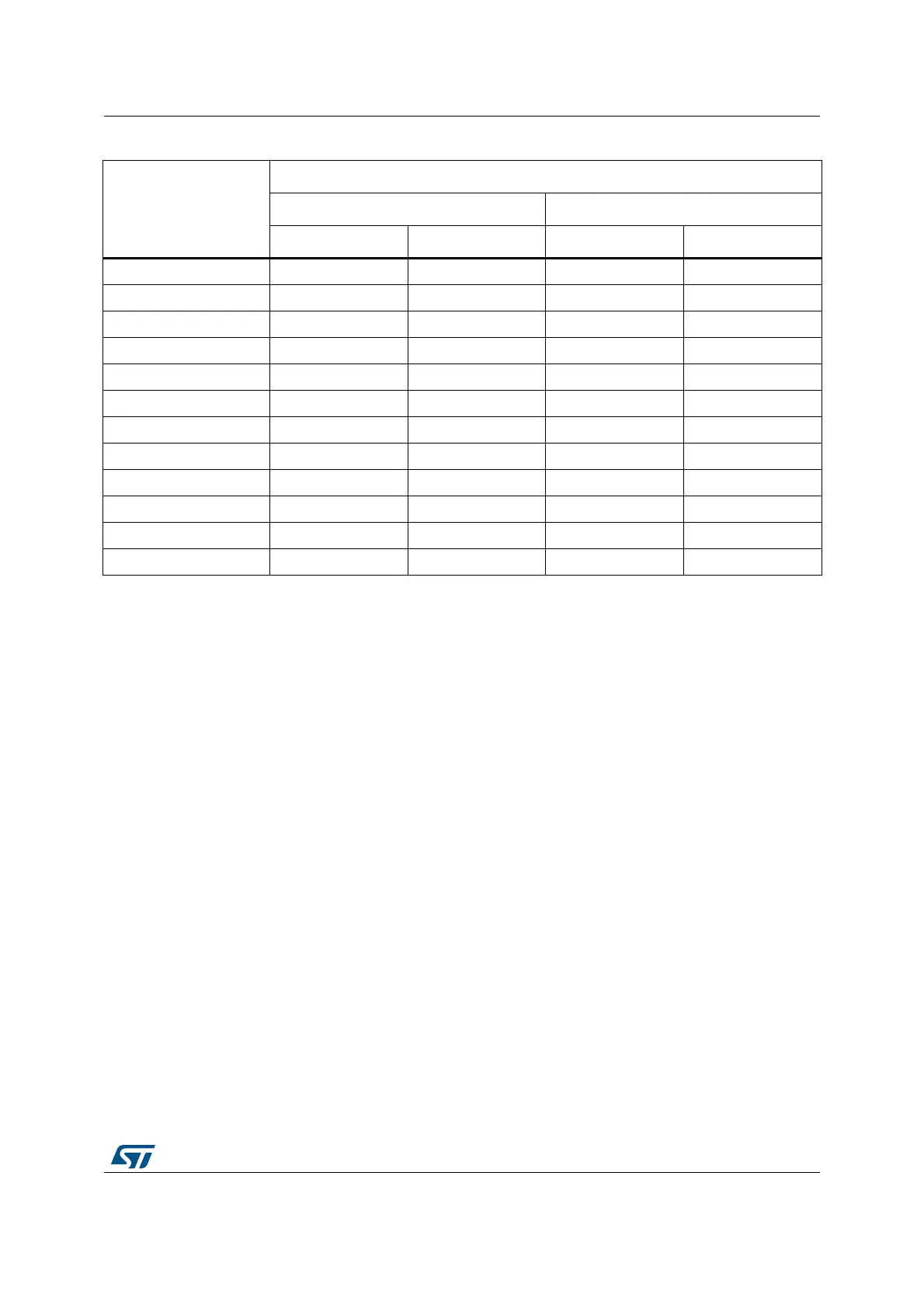
Table 65. Interconnect 19 (continued)
ADC trigger selection
EXTSEL[4:0] or
JEXTSEL[4:0]
ADC triggers signals assignment
ADC1/2 ADC3/4/5
Regular Injected Regular Injected