01/02
4-67
8825/8830 Printer
REP 9.8
Repairs and Adjustments
WARNING
Disposal of the Pin Array is carefully controlled because it is made of a Beryllium Cop-
per alloy. Package the old Pin Array as a returned part. Also, be especially careful of
the very sharp tips on the Pin Array.
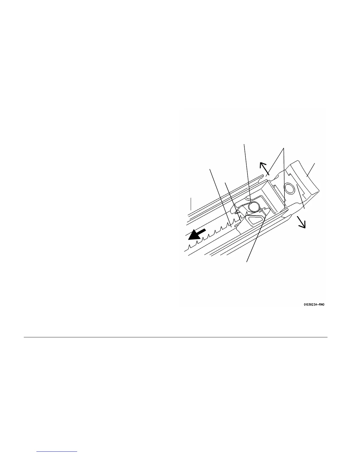
6. (Figure 3): Remove the Charge Scorotron Pin Array.
7. Remove the Torsion Springs from the End Blocks.
Replacement
1. Install the Torsion Springs from the repair kit.
CAUTION
Be careful not to damage the tips of the new Pin Array. Bent tips can cause Print Quality prob-
lems.
2. Install the Pin Array from the repair kit into the End Blocks.
3. Reinstall the End Blocks into the Scorotron Extrusion. Ensure that the Pin Array is posi-
tioned in the Center Support (not shown) of the Scorotron Extrusion.
4. After completing the reassembly, package the Pin Array for return.
Figure 3 Removing the Charge Scorotron Pin Array
4
Repeat Steps 1-3 at the
opposite end and remove
the Pin Array
3
Remove the Pin Array
from the tangs of the tor-
sion spring
2
Pull the Pin Array and lift it
off the stud
1
Spread open the plastic extrusion
and lift out the End Block
Scorotron
Extrusion
Stud
Torsion Spring
End
Block
Grid Channel
Grove

 Loading...


