01/02
6-50
8825/8830 Printer
Molex Connector Repair Procedure
General Procedures
Molex Connector Repair Procedure
Purpose
The purpose of this procedure is to show the approved method of repair or replacement of the
wire terminals in either the Pin Housing Connectors or the Socket Housing Connectors without
damaging them.
CAUTION
The Molex connectors will break easily. Use only approved tools and procedures when extract-
ing modules or terminals, or resetting the terminal locking tabs.
Items Required
600T1825 Extraction Tool
Procedure
1. ( Figure 1): Familiarize yourself with the Molex Extraction Tool components.
Figure 1 Molex Extraction Tool Components
CAUTION
Note the location of the individual module connectors in the housing before removing them.
This will ensure that they are reinstalled correctly after the repair to the terminals is complete.
Failure to position the individual connectors correctly will cause the printer to malfunction,
causing damage.
CAUTION
Use caution when forcing the housing body away from the module connector. Too much force
could cause damage to the housing body.
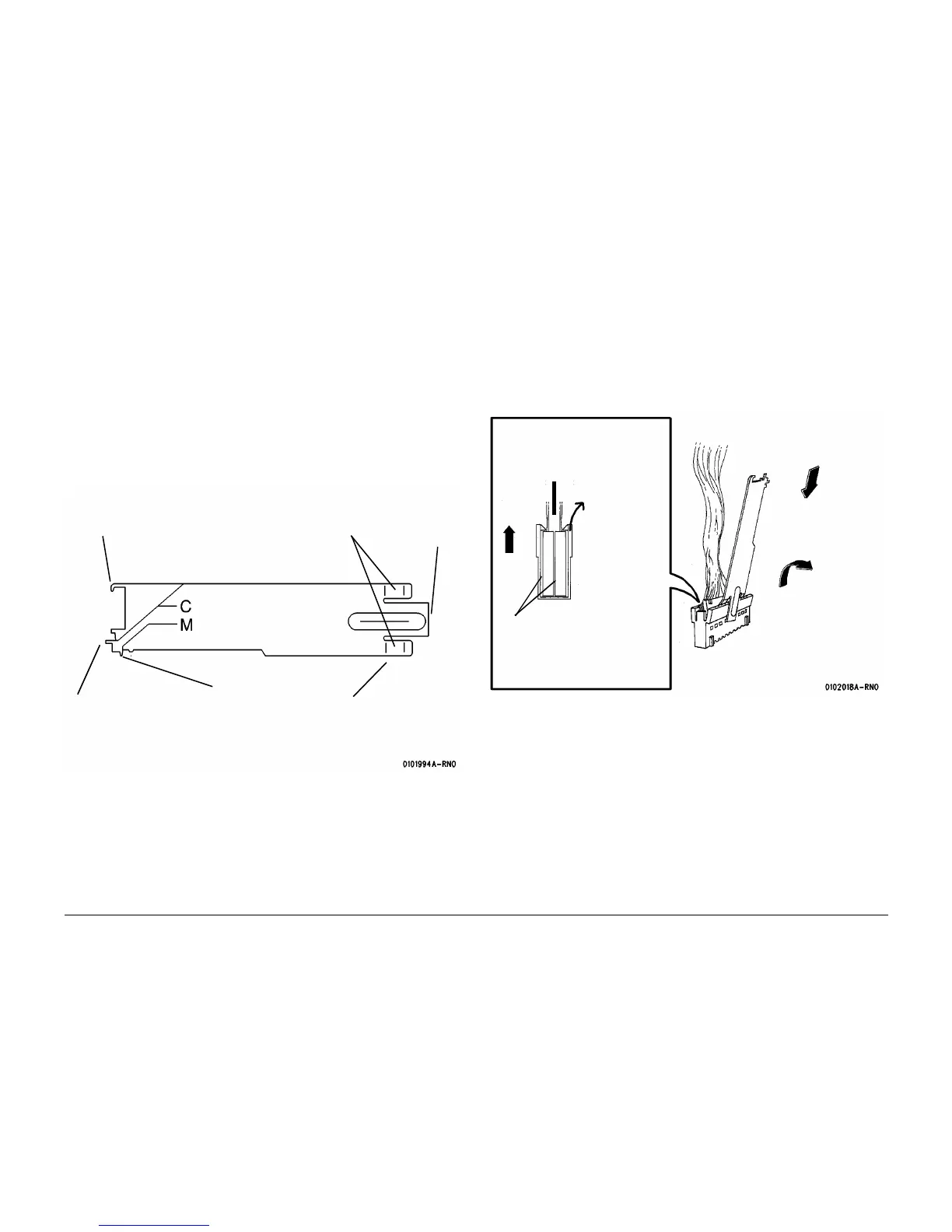
2. ( Figure 2): Remove the individual module connectors from the housing.
Figure 2 Removing the Module Connectors
NOTE: Insert the Extractor Tab until the face of the tool is flush with the connector housing.
3. ( Figure 3):Remove the terminal from the connector.
This protruding tab is used to
release the locking tabs on
the pins while the individual
module connectors remain in
the housing
This protruding tab is
used to release the
locking tabs on the
pins when the individ-
ual module connec-
tors are removed from
the housing
This hook is used to reform the lock-
ing tab on the pin before inserting the
pin into the connector
These flat tabs and
extender are used to
remove the individual
module connectors from
within the housing
Flat tabs
Extender
1
Insert the Extractor Tool
between the housing and
the individual module
connectors
2
Force the housing body
away from the module
connectors while per-
forming the step 3
4
Remove the module connec-
tors from the housing body
Module connectors
3
Ensure that
the tabs on the
housing are
moved clear of
the module
connectors

 Loading...


