01/02
4-103
8825/8830 Printer
ADJ 9.2
Repairs and Adjustments
ADJ 9.2 Electrostatic Series
Purpose
The purpose is to set the drum voltages to obtain good print quality as specified in Section 3 of
this Service Manual. On Printers With TAG 23, it is necessary to establish the correct Average
Light Output (ALO) of the LED Bar in order to set the voltages.
Adjustment
1. If the Printer is Without TAG 23, go to Step 8..
2. (With TAG 23): Raise and secure the Top Cover.
NOTE: In the following steps, “Left” and “Right” describe machine locations as observed when
you are facing the Xerographic Module at the left side of the Printer.
3. (With TAG 23): Look in on the right side of the Image Module for the ALO Label,
attached to either the front or the rear of the LED Bar.
4. (With TAG 23): Record the ALO value as follows.
a. On an early build printer, read the Bar number on the AOL Label and find the Aver-
age Light Output value from Table 1 at the end of this procedure.
b. On a newer printer, read the Average Light Output value directly from the label.
Round the value to the second decimal point. (1.035 becomes 1.04, .983 becomes
.98, for example.)
5. (With TAG 23): Lower the Top Cover.
6. (With TAG 23): Enter Diagnostics.
7. (With TAG 23): Program in the Average Light Output value.
a. Enter code [ 09 03].
b. Enter the ALO value.
c. Press the Enter button in order to store the value in NVM.
d. Press the Exit button two times.
8. Raise and secure the Top Cover.
9. Open the Image Module.
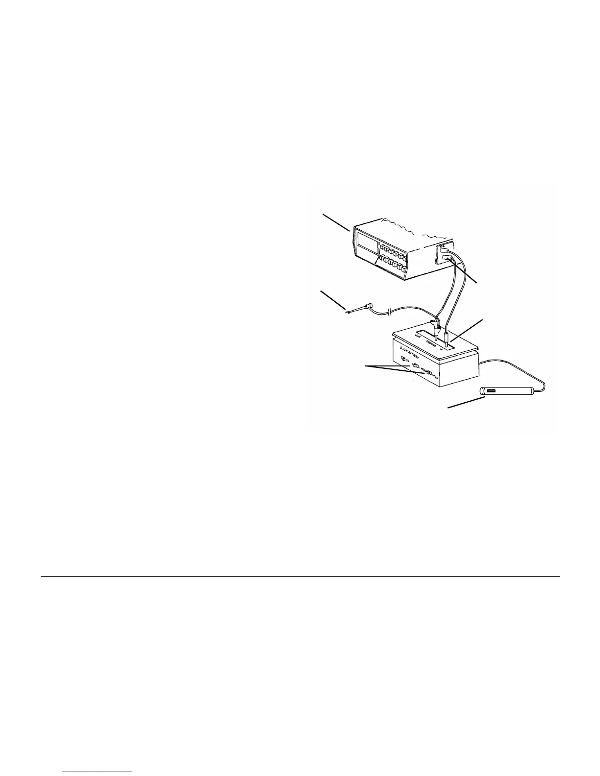
10. ( Figure 1): Prepare the Electrometer and connect it to the DMM.
Figure 1 Connecting the Electrometer to the DMM
NOTE: In the following steps, if the voltage cannot be adjusted check for correct position-
ing of the Electrometer window.
11. Position the Electrometer Probe to measure the voltage on the drum.
a. Install the probe wing onto the Electrometer Probe. Ensure that the window of the
wing is centered over the window of the probe.
b. (Figure 2): Remove the plug from the side of the Image Module.
c. Slide the Electrometer Probe through the hole, into the channel.
d. Determine the center of the Image Module and push the probe along the channel
until the probe window is centered on the Image Module.
Ground
2
Connect the leads
between the DMM
and Electrometer
3
Connect to the
machine frame
4
Select the READ
and (-) positions
Connect Volts
lead from
DMM to HI
1
Set DMM scale to
1000 volts DC
5
Check for correct positioning of
the Electrometer window

 Loading...


