01/02
4-88
8825/8830 Printer
REP 10.1
Repairs and Adjustments
REP 10.1 Heat Rod
Parts List on PL 10.2
WARNING
Switch off the Main Power Switch. Disconnect the Power Cord. Allow the Fuser Assem-
bly to cool before the procedure is performed.
Removal
1. Remove the Stripper Finger Assembly.
2. Perform the Xerographic Module procedure (REP 9.1) through Step 11. This will leave the
Xerographic Module at the Service Position, handles installed, and the Drum Assembly
removed.
NOTE: In the following steps, “Left” and “Right” describe machine locations as observed when
you are facing the Xerographic Module at the left side of the Printer.
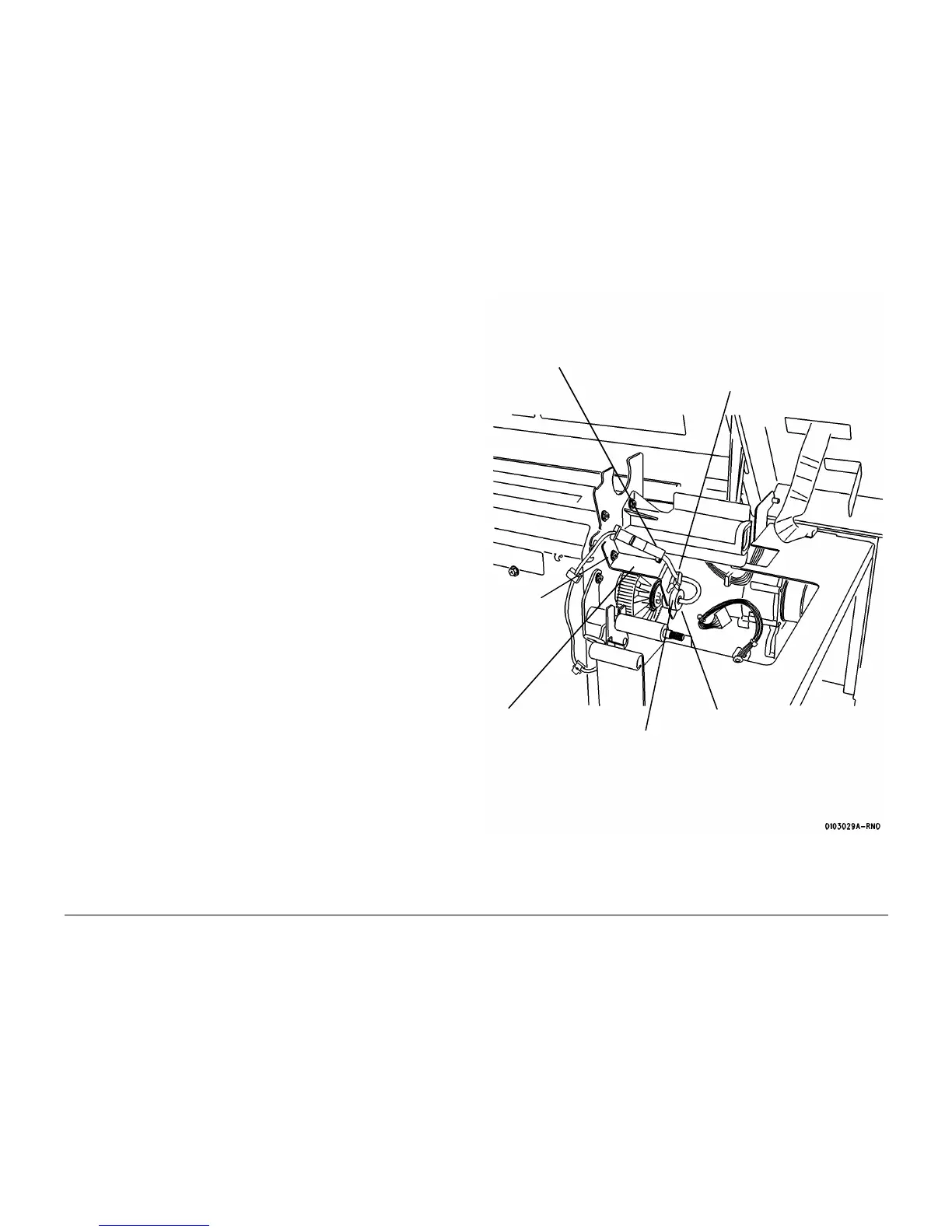
3. (Figure 1): Disconnect the Heat Rod (Right Side).
Figure 1 Removing the Bracket and Grommet (Right Side)
2
Disconnect the con-
nector and straighten
the Heat Rod Wire
1
Remove the Heat
Rod
Wire from the clamp
3
Remove the
screw
4
Remove the bracket
from the grommet
5
Remove the grommet
from the Heat Rod
Wire
Grommet

 Loading...


