01/02
4-43
8825/8830 Printer
REP 9.1
Repairs and Adjustments
REP 9.1 Xerographic Module
Parts List on PL 9.1, PL 10.1
WARNING
Switch off the Main Power Switch. Disconnect the Power Cord.
Removal
1. Loosen the screws and open the Rear Door.
2. Raise and latch the Top Cover.
3. Lift and rotate the Image Module to the Service Position.
4. Lower the Media Transport Cover.
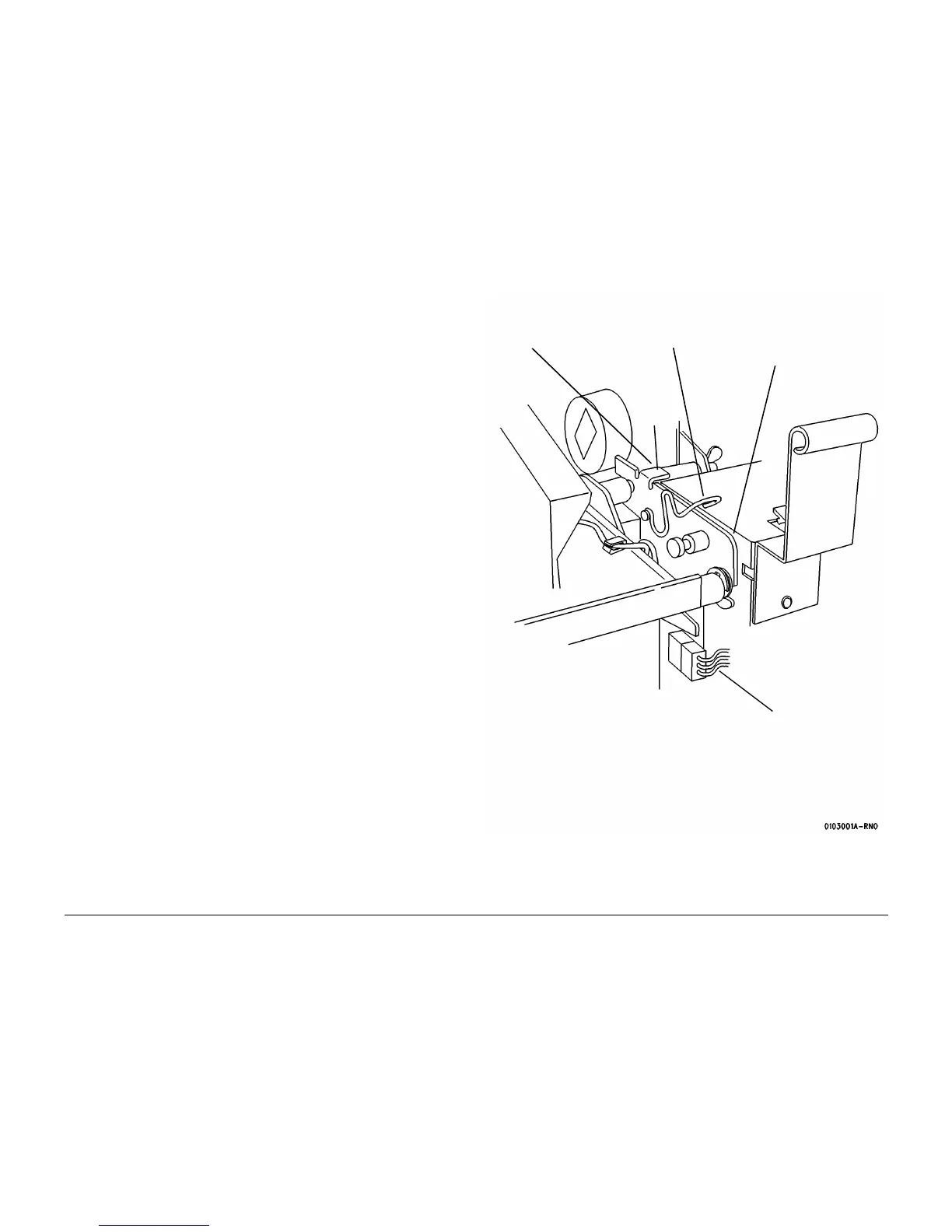
NOTE: Figure 1 shows only the Front Support Bracket.
5. (Figure 1): Prepare the Front and Rear Support Brackets for raising the Xerographic Mod-
ule to the Service Position.
Figure 1 Preparing the Support Bracket
6. Remove the Web Oiler Assembly (REP 10.7).
1
Lift the bracket at the
tab in order to discon-
nect the spring
2
Pull the spring away
from the shaft
3
Push the bracket down
to the horizontal posi-
tion
4
Disconnect A23P1
5
Perform Steps 1
through 3 for the Rear
Support Bracket
Ta b

 Loading...


