01/02
4-93
8825/8830 Printer
REP 10.7, REP 10.8
Repairs and Adjustments
REP 10.7 Web Oiler Assembly
Parts List on PL 9.6
WARNING
Switch off the Main Power Switch. Disconnect the Power Cord.
Removal
1. Loosen the screws and open the Rear Door.
2. Raise and latch the Top Cover.
3. Ensure that there is a clean, flat surface on which to place the Web Oiler Assembly after it
is removed.
4. (Figure 1): Remove the Web Oiler Assembly and place it top down, resting on the han-
dles, on a flat surface.
Replacement
1. At reinstallation, engage the rear lip of the Web Oiler Housing over the metal bracket of
the Xerographic Module.
2. After completing the reassembly, enter diagnostics and perform one of the following
actions.
a. If a new Web Oiler has been installed, initialize the Web Oiler using [1030].
b. If the old Web Oiler is still in the assembly, remove the slack in the web by running
[1033] until the display shows the following: Count = 001
Figure 1 Removing the Web Oiler Assembly
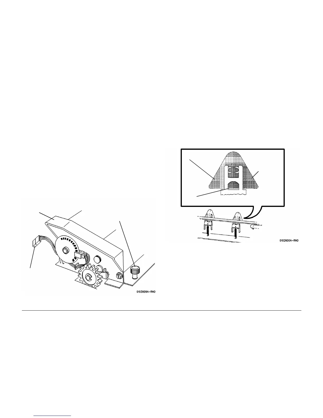
REP 10.8 Stripper Fingers
Parts List on PL 10.4
WARNING
Switch off the Main Power Switch. Disconnect the Power Cord. Allow the Fuser Assem-
bly to cool before the procedure is performed.
Removal
1. Remove the Stripper Finger Assembly.
2. (Figure 1): Remove the Stripper Fingers.
Figure 1 Removing the Stripper Fingers
1
Loosen the two
thumbscrews
3
Holding the handles, rotate the
rear upward. Lift it and remove.
2
Disconnect P/J4
Stripper Finger
Ta b
1
Remove the
Stripper Finger
while pushing
the tab
 Loading...


