01/02
4-66
8825/8830 Printer
REP 9.8
Repairs and Adjustments
REP 9.8 Scorotron Pin Kit
Parts List on PL 9.3
NOTE: These are the instructions to install the Scorotron Pin Kit. The kit contains the following
items:
• Pin Array
• Torsion Spring (2)
• Container
WARNING
Switch off the Main Power Switch. Disconnect the Power Cord.
Removal
1. Loosen the screws and open the Rear Cover.
2. Raise and latch the Top Cover.
3. Rotate the Image Module to the Service Position.
4. (Figure 1): Remove the Charge Scorotron Assembly from the Printer and place it on a flat
surface.
Figure 1 Removing the Charge Scorotron Assembly
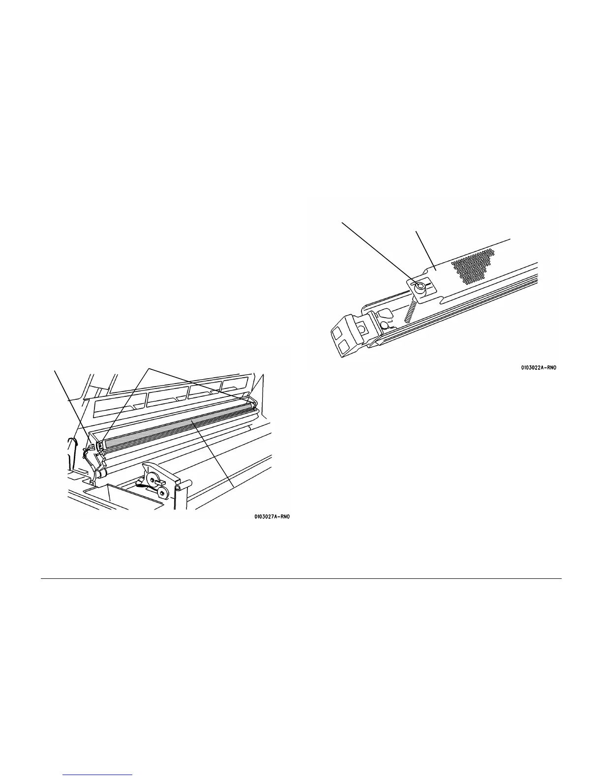
5. (Figure 2): Remove the Grid Channel.
Figure 2 Removing the Grid Channel
1
Disconnect the two
connectors
2
Rotate the screws until they are free of the mount-
ing blocks on the Image Module
3
Remove the Charge
Scorotron Assembly
1
Remove the screws
(both ends)
2
Remove the Grid
Channel

 Loading...


