CS1D Reference Manual (Hardware)
10
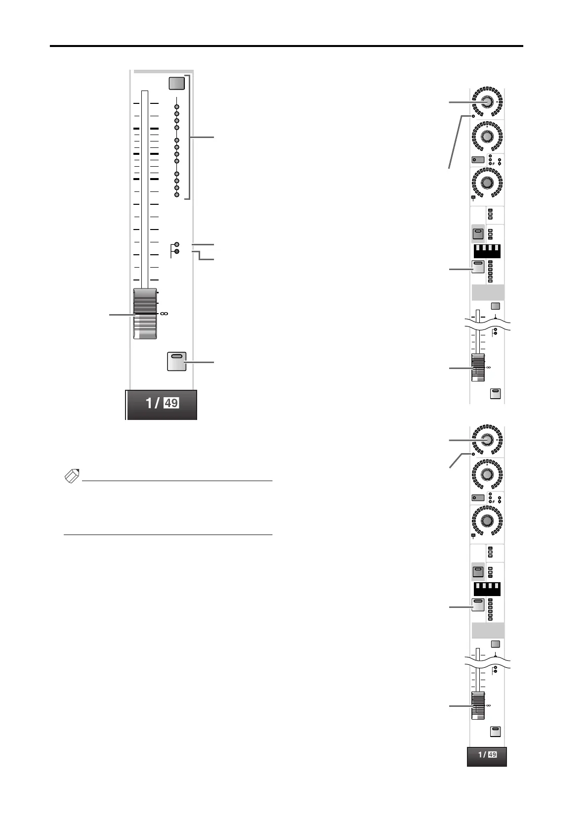
L INPUT fader
This is a 100 mm fader that adjusts the input level of each
input channel. The adjustable range is – ∞ dB – +10 dB.
Hint
In the SELECTED INPUT CHANNEL block FADER
FLIP section, you can exchange (flip) the functions
of the INPUT fader (L) and the INPUT [MIX]
encoder (6) as shown in the following illustrations.
• When the FADER FLIP [CH] switch is on
• When the FADER FLIP [MIX] switch is on
DCA
2
3
1
4
6
7
5
8
10
11
9
SAFE
12
10
5
5
0
10
20
30
40
50
60
RCL
MUTE
CUE
L
N
P
O
M
MIX
ON
100
PAN
TO ST
CLIP
R
+48V
INPUT
INS A
B
L
GAIN
DCA
-68
+
THR
-
COMP
+
THR
-
CLIP
6
12
18
2
1
SAFE
30
60
GATE
+10
10
30
40
50
60
RCL
MUTE
ON
CUE
SEL
If a VARI type MIX bus is selected, this
encoder will adjust the send level to
that MIX bus. If a FIX type MIX bus is
selected, only the LED at the
® posi-
tion will light, and the encoder will be
disabled.
This indicates the on/off status of the
signal that is sent from the input chan-
nel to the currently selected MIX bus.
This turns the input channel on/off.
This adjusts the input level of the input
channel.
MIX
ON
100
PAN
TO ST
CLIP
R
+48V
INPUT
INS A
B
L
GAIN
DCA
-68
+
THR
-
COMP
+
THR
-
CLIP
6
12
18
2
1
SAFE
30
60
GATE
+10
10
30
40
50
60
RCL
MUTE
ON
CUE
SEL
This adjusts the input level of the input
channel.
This indicates the on/off status of the
input channel.
This is an on/off switch for the signal
that is sent from the input channel to
the currently selected MIX bus.
If a VARI type MIX bus is selected, this
fader will adjust the send level to that
MIX bus. If a FIX type MIX bus is
selected, the fader will be fixed at the
0 dB position and will have no effect.