SELECTED INPUT CHANNEL block
23
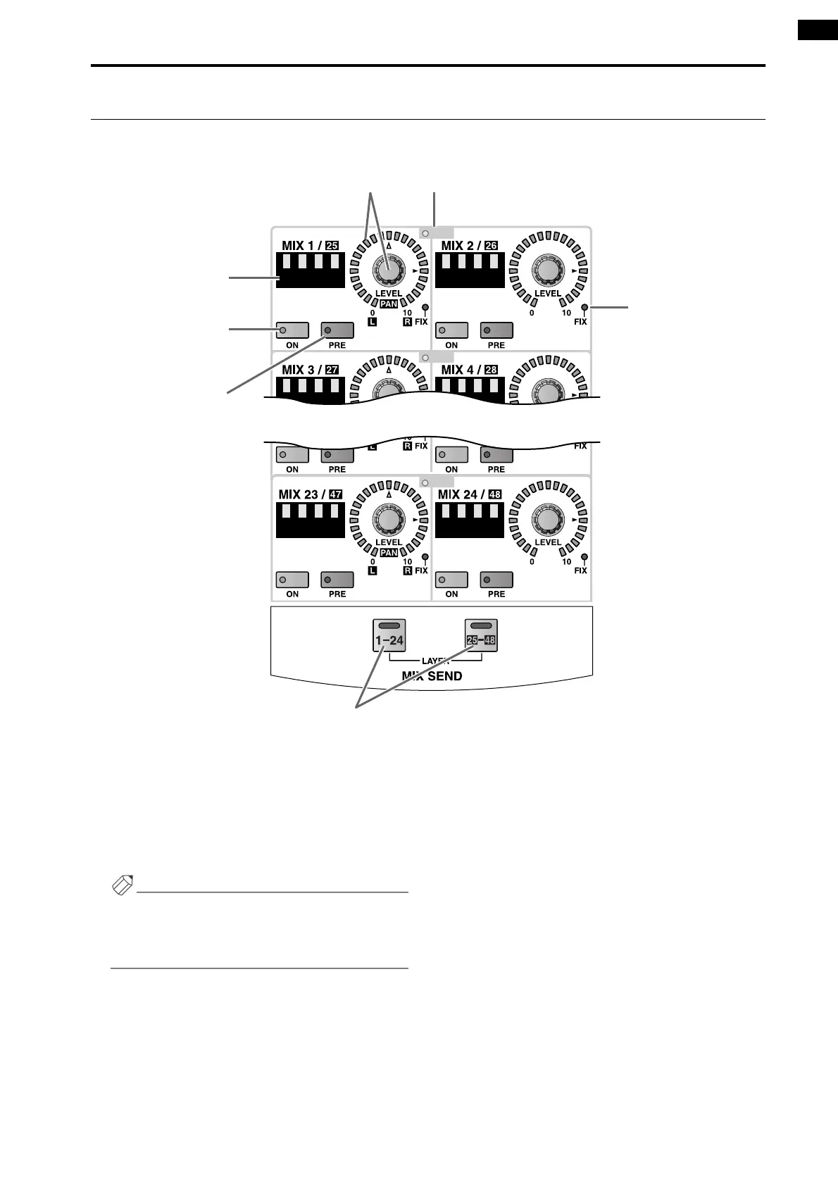
MIX SEND section
In this section, the signals sent from the currently selected channel to MIX buses 1–48 can be switched on/off, and their
send levels adjusted.
1 MIX SEND [PAIR] LED
This LED will light to indicate two adjacent odd and
even-numbered MIX buses 1–48 (MIX buses 1/2, 3/
4, ...) that are paired.
Mix bus pairing can be set or defeated on the console
by the MIX OUTPUT block MIX [SEL] switch, or in
the display (PAN ROUTING function etc.).
Hint
Before you perform this procedure, use the MIX
SEND LAYER [1-24]/[25-48] switches (7) to select
either MIX buses 1-24 or MIX buses 25-48 as the
send destination MIX buses.
2 MIX SEND [LEVEL/PAN] encoder and LEDs
This encoder sets the send level of the signal that is
sent from the currently selected channel to a MIX
bus that is set to VARI.
The range of adjustment is – ∞ dB – +10 dB, and the
approximate current value is shown by the perimeter
LEDs.
When the LED at the ® symbol is lit, the level is
nominal (0 dB).
However in the case of FIX type MIX buses, only the
LED at the ® position of the input channel will light,
and the MIX SEND [LEVEL] encoder will be dis-
abled.
If the send destination MIX bus is paired, the
encoder for the left-hand MIX bus will function as
the MIX SEND [PAN] encoder, and the encoder for
the right-hand MIX bus will function as the MIX
SEND [LEVEL] encoder. The approximate current
value for each will be shown by the perimeter LEDs
around each encoder.
PAIR
PAIR
PAIR
12
3
4
5
7
6