6
Connections (Standard mode)
This section explains connections for Standard mode, in which one console (CS1D) is connected to one engine (DSP1D-
EX {DSP1D}).
Connecting the console and engine (Standard mode)
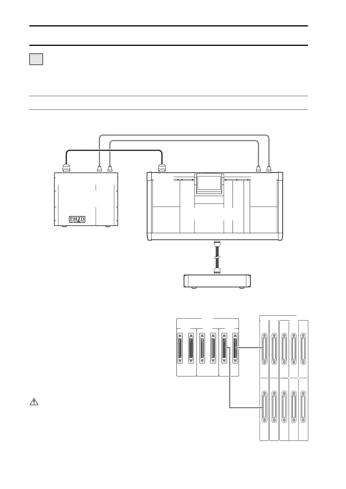
The following diagram shows typical connections between the console and engine for Standard mode.
1
Digital input/output connections
Use the included D-sub half pitch 68 pin cable to
connect the DIGITAL I/O ENGINE A connector of
the console to the CONSOLE I/O connector of the
engine.
These connectors transmit and receive multi-channel
digital audio signals.
The console and engine each have two identical digi-
tal input/output connectors, numbered 1 and 2.
These two sets of connectors are completely identi-
cal, and the system will operate normally if just one
set is connected. However, you may connect both 1
and 2 so that one of them can be used as a backup.
You must connect the identically-numbered con
-
nectors of the console and engine to each other. If
differently-numbered connectors are connected to
each other, the system will not function correctly.
This method of connection is recommended for
most cases.
DSP
x1x1
1
3
POWER SUPPLY (PW1D)
ENGINE A
2
ENGINE A
DC POWER
INPUT A
IN OUT
IN OUT
CONSOLE (CS1D)
ENGINE A
(DSP1D-EX{DSP1D})
CONTROL
I/O
CONSOLE
I/O
DIGITAL
I/O
CONTROL
I/O
1IN531
2 OUT 6 4 2
OUTPUT
CONSOLE
I/O
CASCADE
DIGITAL I/O
2
CONSOLE
1 2121
ENGINE B
DIGITAL I/O
ENGINE A
Console (CS1D)
Engine
(DSP1D-EX {DSP1D})