Parameter List
10
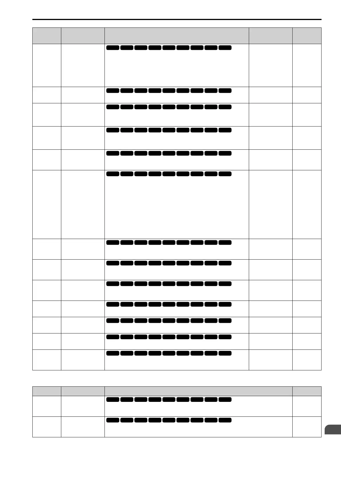
10.10 H: Terminal Functions
YASKAWA ELECTRIC SIEP C710617 05F YASKAWA AC Drive GA700 Technical Manual 561
No.
(Hex.)
Name Description
Default
(Range)
Ref.
H3-09
(0417)
Terminal A2 Signal
Level Select
Sets the input signal level for MFAI terminal A2.
0 : 0-10V (LowLim=0)
1 : -10 to +10V (Bipolar Reference)
2 : 4 to 20 mA
3 : 0 to 20 mA
2
(0 - 3)
915
H3-10
(0418)
Terminal A2
Function Selection
Sets a function for MFAI terminal A2.
0
(0 - 32)
915
H3-11
(0419)
RUN
Terminal A2 Gain
Setting
Sets the gain of the analog signal input to MFAI terminal A2.
100.0%
(-999.9 - +999.9%)
916
H3-12
(041A)
RUN
Terminal A2 Bias
Setting
Sets the bias of the analog signal input to MFAI terminal A2.
0.0%
(-999.9 - +999.9%)
916
H3-13
(041B)
Analog Input
FilterTime
Constant
Sets the time constant to apply a primary delay filter to the MFAI
terminal.
0.03 s
(0.00 - 2.00 s)
916
H3-14
(041C)
Analog Input
Terminal Enable
Sel
Sets the enabled terminal or terminals when H1-xx = C [MFDI
Function Select = Analog Terminal Enable Selection] is ON.
1 : Terminal A1 only
2 : Terminal A2 only
3 : Terminals A1 and A2
4 : Terminal A3 only
5 : Terminals A1 and A3
6 : Terminals A2 and A3
7 : Terminals A1, A2, and A3
7
(1 - 7)
916
H3-16
(02F0)
Terminal A1 Offset
Sets the offset level for analog signals input to terminal A1. Usually
it is not necessary to change this setting.
0
(-500 - +500)
917
H3-17
(02F1)
Terminal A2 Offset
Sets the offset level for analog signals input to terminal A2. Usually
it is not necessary to change this setting.
0
(-500 - +500)
917
H3-18
(02F2)
Terminal A3 Offset
Sets the offset level for analog signals input to terminal A3. Usually
it is not necessary to change this setting.
0
(-500 - +500)
917
H3-40
(0B5C)
Mbus Reg 15C1h
Input Function
Sets the MEMOBUS AI1 function.
F
(4 - 2F)
917
H3-41
(0B5F)
Mbus Reg 15C2h
Input Function
Sets the MEMOBUS AI2 function.
F
(4 - 2F)
917
H3-42
(0B62)
Mbus Reg 15C3h
Input Function
Sets the MEMOBUS AI3 function.
F
(4 - 2F)
917
H3-43
(117F)
Mbus Reg Inputs
FilterTime Const
Sets the time constant to apply a primary delay filter to the
MEMOBUS analog input terminal.
0.00 s
(0.00 - 2.00 s)
918
■ H3-xx: MFAI Function Selections
Setting Function Description Ref.
0 Frequency
Reference
The input value from the MFAI terminal set with this function becomes the master
frequency reference.
918
1 Frequency Gain
The drive multiplies the analog frequency reference with the input value from the MFAI
set with this function.
918