Parameter Details
11
11.9 L: Protection Functions
YASKAWA ELECTRIC SIEP C710617 05F YASKAWA AC Drive GA700 Technical Manual 963
• L2-29 = 1 [KEB Method Selection = Single Drive KEB Ride-Thru 2]
• L3-04 = 2 [Decel Stall Prevention Selection = Automatic Decel Reduction]
• L3-11 = 1 [OV Suppression Function Select = Enabled]
• H1-xx = 7A or 7B [MFDI Function Select = KEB Ride-Thru 2 (N.O./N.C.)]
Note:
When Auto-Tuning changes the value of E2-11 [Motor Rated Power (kW)], the drive will automatically set this parameter to the value
for a Yaskawa standard motor (4 poles). When you use a PM motor, the drive uses the value in E5-01 [PM Motor Code Selection] to
change this parameter.
Automatically Adjust Parameters
Execute the Inertia Tuning process when A1-02 = 3 or 7 [Control Method Selection = Closed Loop Vector
Control or PM Closed Loop Vector Control]. Parameters are automatically adjusted.
Manually Adjust Parameters
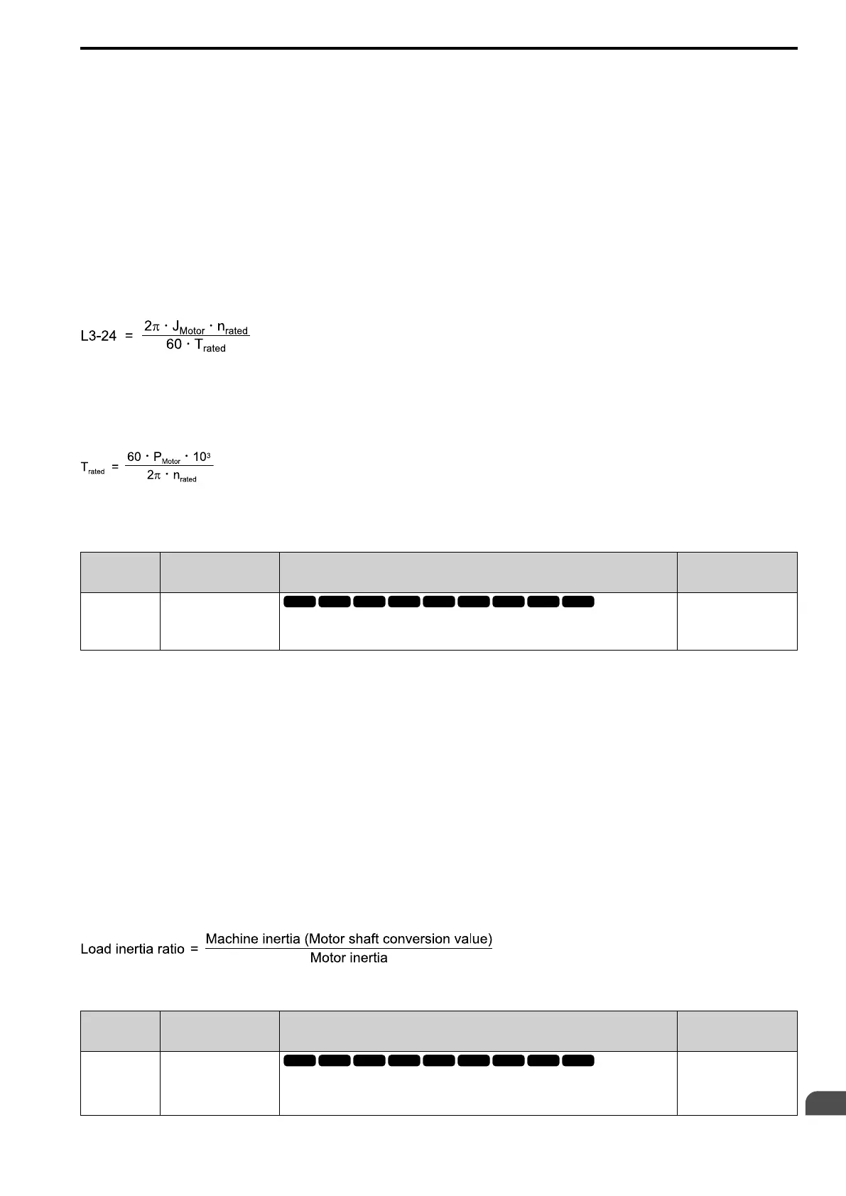
Use this formula to find the motor acceleration time:
• J
Motor
= Moment of inertia of motor (kg m
2
)
• n
rated
= Motor rated speed (min
-1
, r/min)
• T
rated
= Motor rated torque (N∙m)
The rated torque is calculated using the following expression.
P
Motor
= Motor Rated Power (kW)
■ L3-25: Load Inertia Ratio
No.
(Hex.)
Name Description
Default
(Range)
L3-25
(046F)
Expert
Load Inertia Ratio
Sets the ratio between motor inertia and machine inertia.
1.0
(1.0 - 1000.0)
Set one of these parameters to enable L3-25:
• L2-29 = 1 [Kinetic Energy Backup Method = Single Drive KEB Ride-Thru 2]
• L3-04 = 2 [Stall Prevention during Decel = Intelligent (Ignore Decel Ramp)]
• L3-11 = 1 [Overvoltage Suppression Select = Enabled]
• H1-xx = 7A or 7B [MFDI Function Select = KEB Ride-Thru 2 Activate (N.C./N.O.)]
Note:
• If you set this value incorrectly when L2-29 = 1, H1-xx = 7A or 7B, or L3-11 = 1, it can cause large current ripples and ov
[Overvoltage], Uv1 [DC Bus Undervoltage], or oC [Overcurrent]faults.
• KEB Tuning will automatically set this value.
Automatically Adjust Parameters
Do Inertia Tuning when A1-02 = 3 or 7 [Control Method Selection = Closed Loop Vector or PM Closed Loop
Vector]. The drive will automatically adjust parameters.
Manually Adjust Parameters
Use this formula to find the load inertia ratio:
■ L3-26: Additional DC Bus Capacitors
No.
(Hex.)
Name Description
Default
(Range)
L3-26
(0455)
Expert
Additional DC Bus
Capacitors
Sets the capacity for external main circuit capacitors. Sets this parameter
when you use the KEB Ride-Thru function. Usually it is not necessary to
change this setting.
0 μF
(0 to 65000 μF)