11.9 L: Protection Functions
970 YASKAWA ELECTRIC SIEP C710617 05F YASKAWA AC Drive GA700 Technical Manual
Figure 11.143 Overtorque Detection Time Chart
Note:
The drive applies a hysteresis of approximately 10% of the drive rated output current or the motor rated torque to the overtorque/
undertorque detection function.
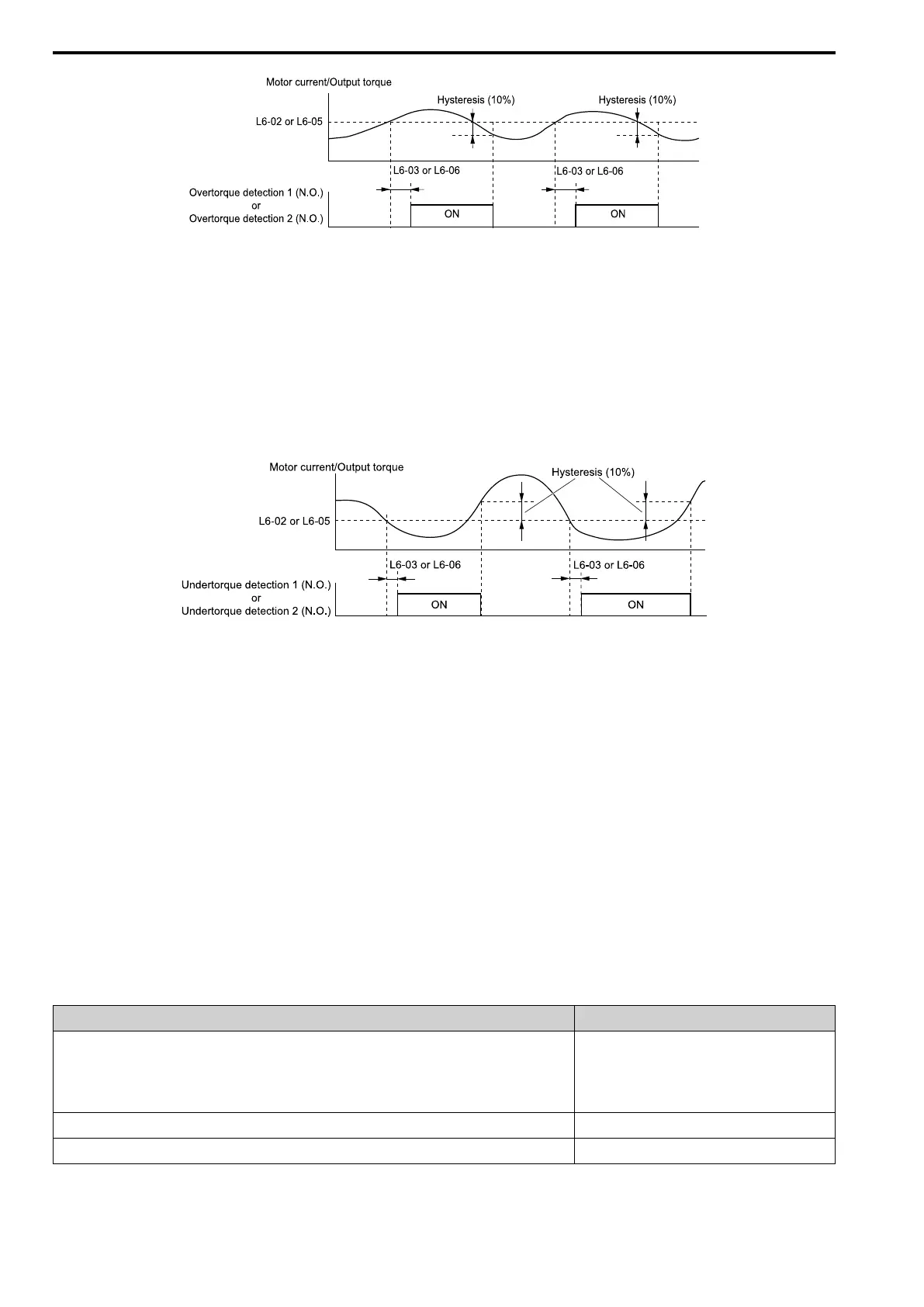
Undertorque Detection Time Chart
When you use Overtorque/Undertorque Detection 1, the drive detects undertorque if the motor current or motor
torque is less than or equal to the detection level set in L6-02 for the time set in L6-03.
Parameter L6-01 sets the operation after detection. When you use Overtorque/Undertorque Detection 2, set the
operation in L6-05, L6-06, and L6-04.
Set the terminal that outputs an alarm in H2-01 to H2-03.
Figure 11.144 Undertorque Detection Time Chart
Note:
The drive applies a hysteresis of approximately 10% of the drive rated output current or the motor rated torque to the overtorque/
undertorque detection function.
■ Mechanical Weakening Detection
The Mechanical Weakening Detection function detects the mechanical weakening of a machine that can cause
overtorque or undertorque because of motor speed and total drive operation time.
The drive activates the function if the drive total operation time is longer than the time set in L6-11 [Mech Fatigue
Hold Off Time]. You can use U4-01 [Cumulative Ope Time] to monitor the total operation time.
Parameter Settings
The drive detects Mechanical Weakening if overtorque or undertorque occur during the speed range set in L6-08
[Mechanical Fatigue Detect Select] and L6-09 [Mech Fatigue Detect Speed Level] for the length of time set in
L6-10 [Mech Fatigue Detect Delay Time]. The drive uses L6-01 to L6-03 [Torque Detection 1 Setting Parameter]
to detect oL5 [Mechanical Weakening Detection 1] or UL5 [Mechanical Weakening Detection 2]. Parameter L6-
08 sets the operation after detection.
Set the terminal that outputs the fault in H2-01 to H2-03 [MFDO Function Select].
Table 11.75 Mechanical Weakening Detection Settings Parameters
Configuration Parameter Mechanical Deterioration Detection
MFDO Function Select
• Terminals M1-M2
• Terminals M3-M4
• Terminals M5-M6
H2-01, H2-02, and H2-03 = 22
Operation Selection after Detection L6-08
Detection Start Time L6-11
 Loading...


