281
Corrective Maintenance
Ribbon Take-up Spindle
8/9/07 ZM400/ZM600 Maintenance Manual 14207L-001 A
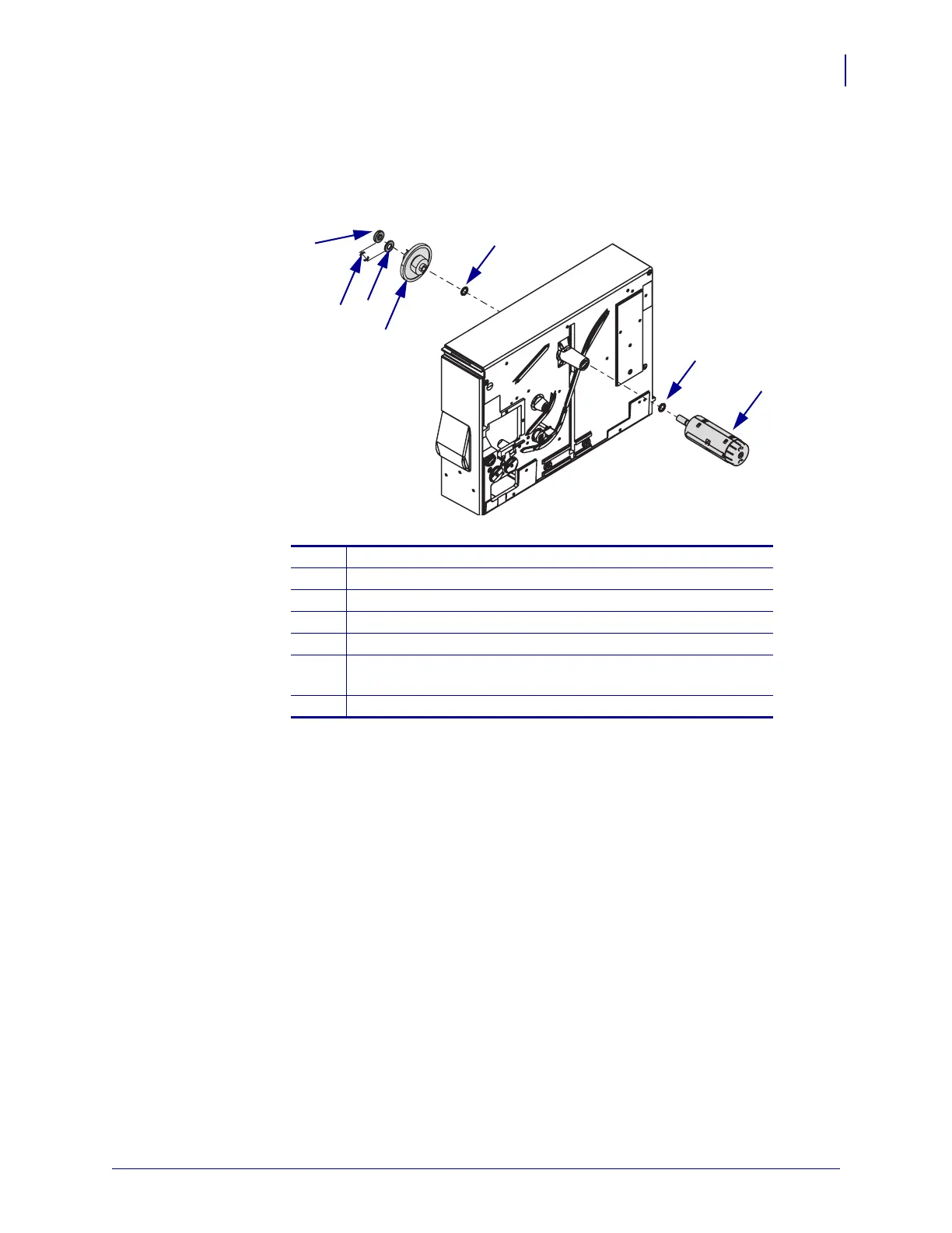
3. See Figure 145. Remove the plastic thrust washer, clutch gear assembly, and washer(s)
from the shaft of the ribbon take-up spindle assembly.
Figure 145 • Remove the RTU Spindle
4. From the media side, remove the ribbon take-up assembly and washer.
Install the New Ribbon Take-up Spindle Assembly
1. See Figure 145. Slide the washer onto the new ribbon take-up assembly.
2. From the media side, slide the ribbon take-up assembly and washer through the main
frame.
3. On the electronics side, place the washer(s), gear clutch assembly, plastic thrust washer,
and collar onto the end of the ribbon take-up assembly shaft.
4. Place a 0.500 mm feeler gauge between the thrust washer and the collar. From the media
side, push in on the ribbon take-up spindle. Tighten the two screws in the collar and ensure
the ribbon take-up spindle turns freely.
1
Ribbon take-up spindle assembly
2
Washer
3
Washer(s)
4
Clutch gear assembly
5
Thrust washer
6
Place a 0.500 mm feeler gauge between the thrust washer and
the collar.
7
Collar
1
2
3
4
5
7
6
 Loading...