Corrective Maintenance
Printhead Cables
186
14207L-001 A ZM400/ZM600 Maintenance Manual 8/9/07
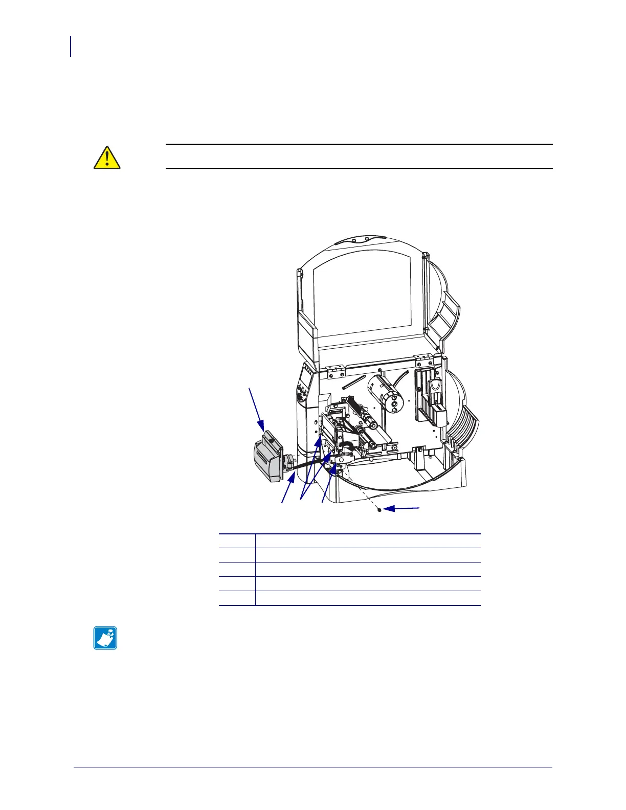
Remove the Cutter Assembly
1. See Figure 63. Unlatch the printhead and turn the latch assembly clockwise to remove the
cutter mounting screw.
2.
Figure 63 • Remove the Cutter Assembly
3. Slide the cutter assembly to the left then lift up and remove the assembly from the platen
assembly hooks.
4. Go to step 4 on page 177.
Caution • The cutter blade is sharp. Do not touch or rub the blade with your fingers.
Remove the cutter mounting screw.
1
Cutter assembly
2
Mounting screw
3
Printhead latch
4
Platen assembly hooks (2)
5
Cutter harness
Note • The cutter guard does not need to be removed from the cutter assembly during this
procedure.
2
3
5
1
4
 Loading...