291
Corrective Maintenance
Printhead Conversion
8/9/07 ZM400/ZM600 Maintenance Manual 14207L-001 A
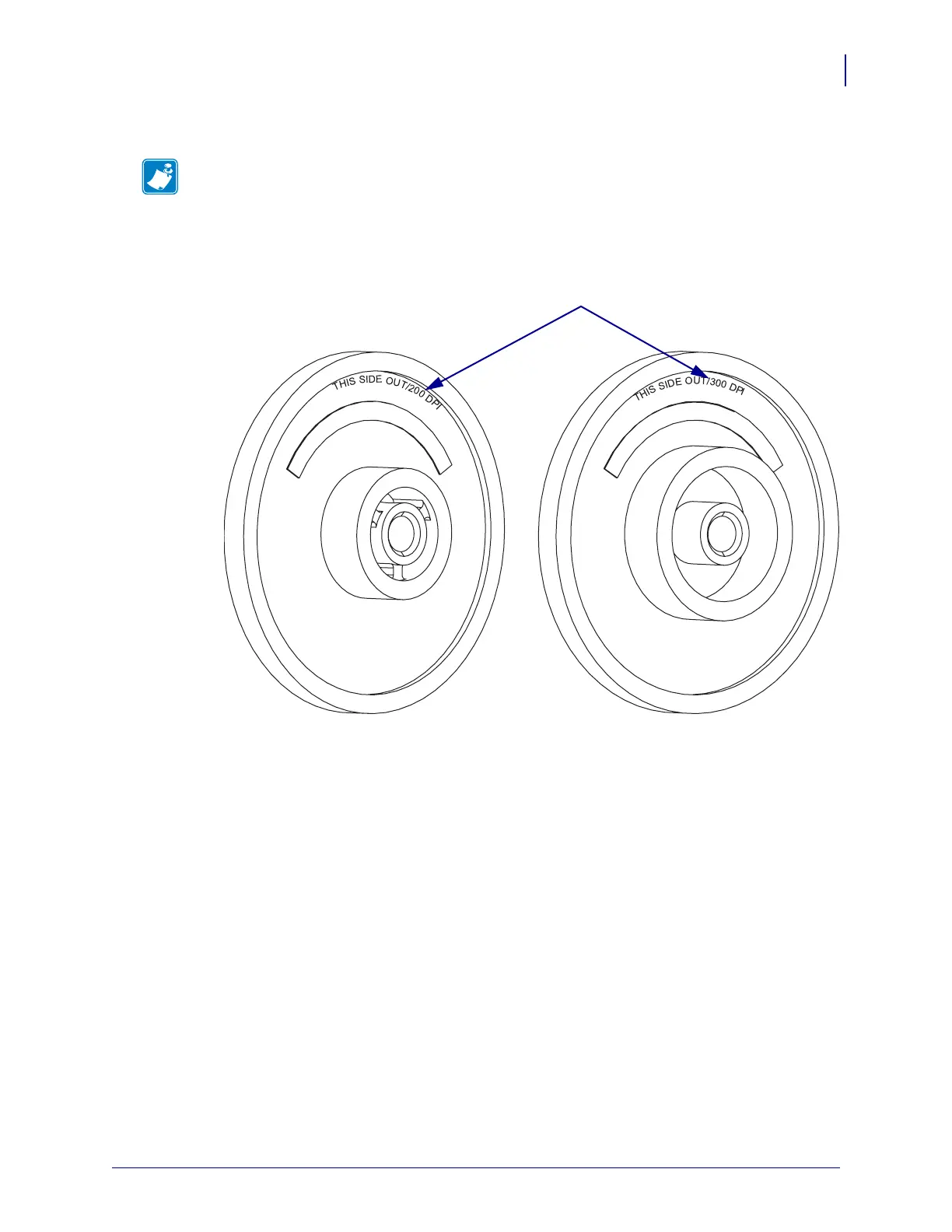
8. See Figure 156. Turn the compound gear around to the proper dpi.
Figure 156 • Compound Gear DPI Location
Reinstall the Compound Gear and Gear Cover
1. See Figure 154 on page 289. With the proper side facing out slide the compound gear into
the printer. Ensure that the gears mesh.
2. Ensure all gears mesh together.
3. Align the gear cover and slide it back into place.
4. Install the mounting screw in the proper hole in the gear cover, through the compound
gear, and then into the proper mounting hole in the main frame.
5. Tighten the mounting screw.
Note • There is a statement on both sides of the compound pulley.
THIS SIDE OUT/200 dpi. and THIS SIDE OUT/300 DPI. THIS SIDE OUT/300 DPI is
also used for 600 dpi.
DPI Statement
 Loading...