Corrective Maintenance
Control Panel
392
14207L-001 A ZM400/ZM600 Maintenance Manual 8/9/07
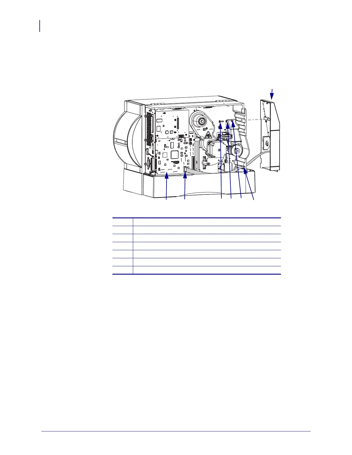
3. See Figure 249. Disconnect the control panel cable from P29 on the main logic board
(MLB).
Figure 249 • Remove the Control Panel
4. Remove the mounting screw, split lock washer, and star lock washer securing the control
panel.
5. Remove the control panel while carefully guiding the control panel cable out of the
printer.
Install the New Control Panel
1. See Figure 249. Remove the new control panel from the antistatic bag.
2. Guide the control panel cable into the printer.
3. Align the new control panel and then install the star lock washer, split lock washer, and
mounting screw and tighten.
4. Connect the control panel cable to P29 on the MLB.
5. See Figure 248 on page 391. Fold the control panel cable over itself to take up the slack
and then slide it under the cable clip.
1
Control panel
2
Access hole
3
Star lock washer
4
Split lock washer
5
Mounting screw
6
Control panel cable
7
Main logic board (MLB)
1
4
3
5
6
7
2
 Loading...