EasyManuals Logo

Zebra ZM400 Series User Manual

Zebra ZM400 Series
470 pages
To Next Page IconTo Next Page
To Previous Page IconTo Previous Page
Page #401 background imageLoading...
Page #401 background image
401
Corrective Maintenance
Main Logic Board
8/9/07 ZM400/ZM600 Maintenance Manual 14207L-001 A
Remove the Old MLB
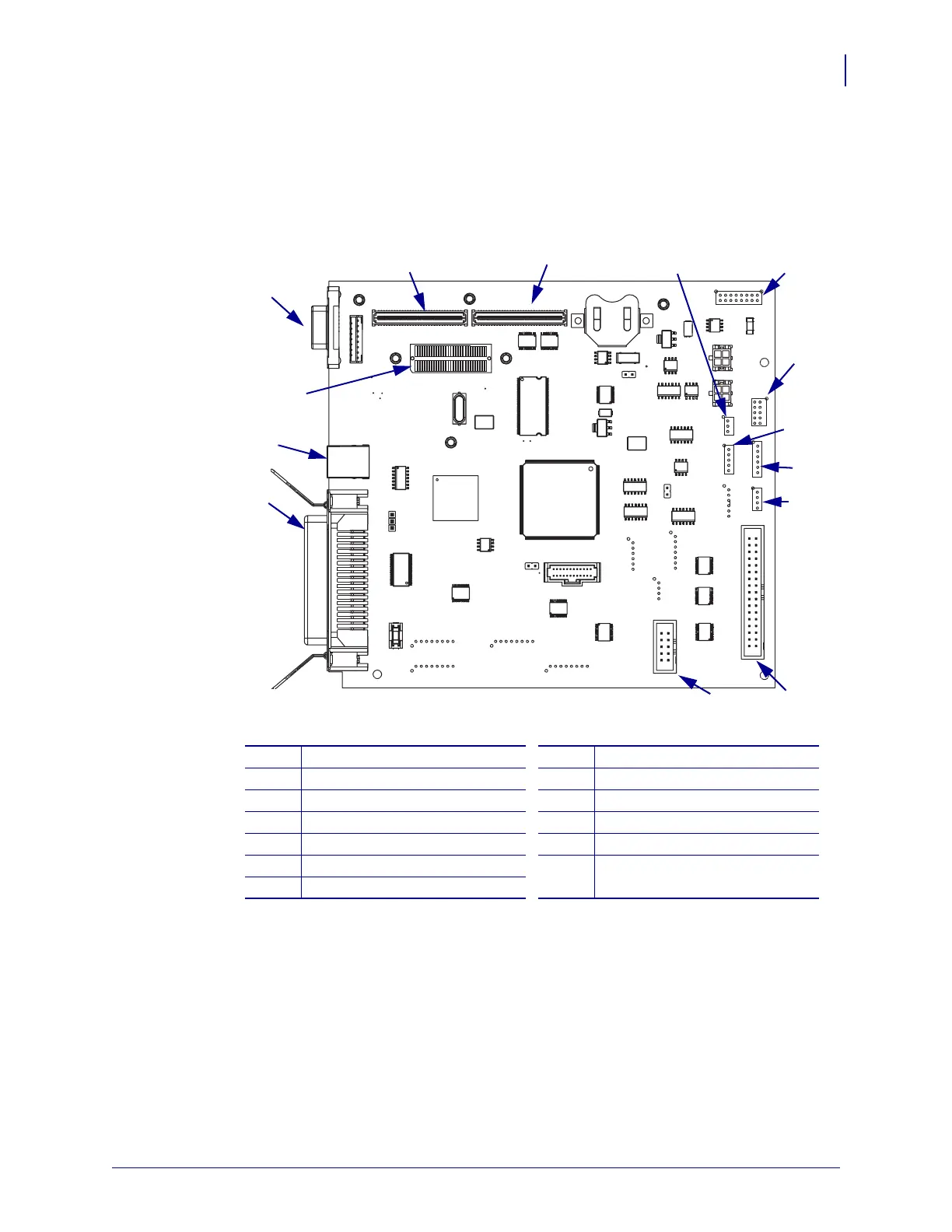
1. See Figure 259. Unplug ribbon cables and small wire connections.
Figure 259 • Main Logic Board Assembly Connection Locations
J1
Serial port
P23
PCMCIA
J2
Parallel port
P24
PCMCIA
J4
Wired ethernet
P25
Power
P4
Ribbon/Head open sensor
P26
Liner Take-up/Cutter/Rewind
P7
Reflective sensor
P29
Control panel
P9
Transmissive sensor
P36
USB
P19
Printhead data
J4
P24
P26
P7
P9
P4
P29
P19
J1
J2
J4
P23
P36
P25
J3

Table of Contents

Questions and Answers:

Question and Answer IconNeed help?

Do you have a question about the Zebra ZM400 Series and is the answer not in the manual?

Zebra ZM400 Series Specifications

General IconGeneral
Max Print Width4.09 inches (104 mm)
Max Print Speed10 inches per second (254 mm per second)
Print MethodThermal Transfer/Direct Thermal
Resolution203 dpi (8 dots/mm)
ConnectivityUSB 2.0, Serial RS-232, Parallel, Internal Ethernet (10/100), optional wireless
Media Width1"/25.4 mm to 4.5"/114 mm
Media Length0.25 to 39 inches (6 to 991 mm)
Media Thickness0.0023"/0.058 mm to 0.010"/0.25 mm
Ribbon Width1"/25.4 mm to 4.33"/110 mm
Ribbon Length1476 feet (450 m)
Supported Media TypesContinuous, die-cut, notch, black-mark
Operating Temperature40°F to 105°F (5°C to 40°C)
Storage Temperature-40°F to 140°F (-40°C to 60°C)

Related product manuals