Corrective Maintenance
Ribbon Take-up Spindle
282
14207L-001 A ZM400/ZM600 Maintenance Manual 8/9/07
Reinstall the Gear Cover
1. See Figure 143 on page 279. With the marked side facing out, slide the compound gear
into the printer. Ensure that the gears mesh.
2. Align the gear cover and slide it back into place.
3. Install the mounting screw in the proper hole in the gear cover, then through the
compound gear, and then into the proper mounting hole in the main frame.
4. Tighten the mounting screw.
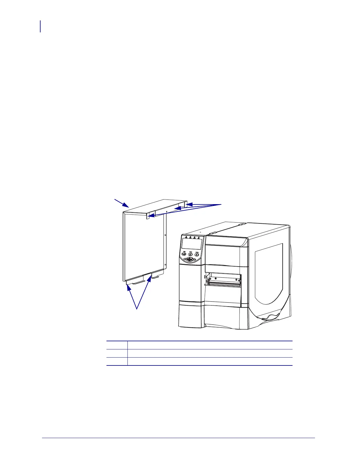
Reinstall the Electronics Cover
1. See Figure 146. Install the electronics cover by aligning it and sliding down, ensuring the
lower flange is inside the base and the upper flange is between the main frame and the
media door.
Figure 146 • Locate the Upper and Lower Flanges
2. See Figure 140 on page 277. Install the four mounting screws.
3. See Figure 139 on page 276. Open the media door.
4. Install the electronics cover mounting screw and lock washer.
5. Reconnect the AC power cord and data cables and then torn on (l) the printer.
1
Electronics Cover
2
Upper Flanges (3)
3
Lower Flanges (2)
2
1
3
 Loading...