11. Integration rod
Image 11-14
7. Fasten the set screw B which you released in step 3.
8. Loosen the two set screws A as illustrated. Use a 2 mm Allen key.
A
A
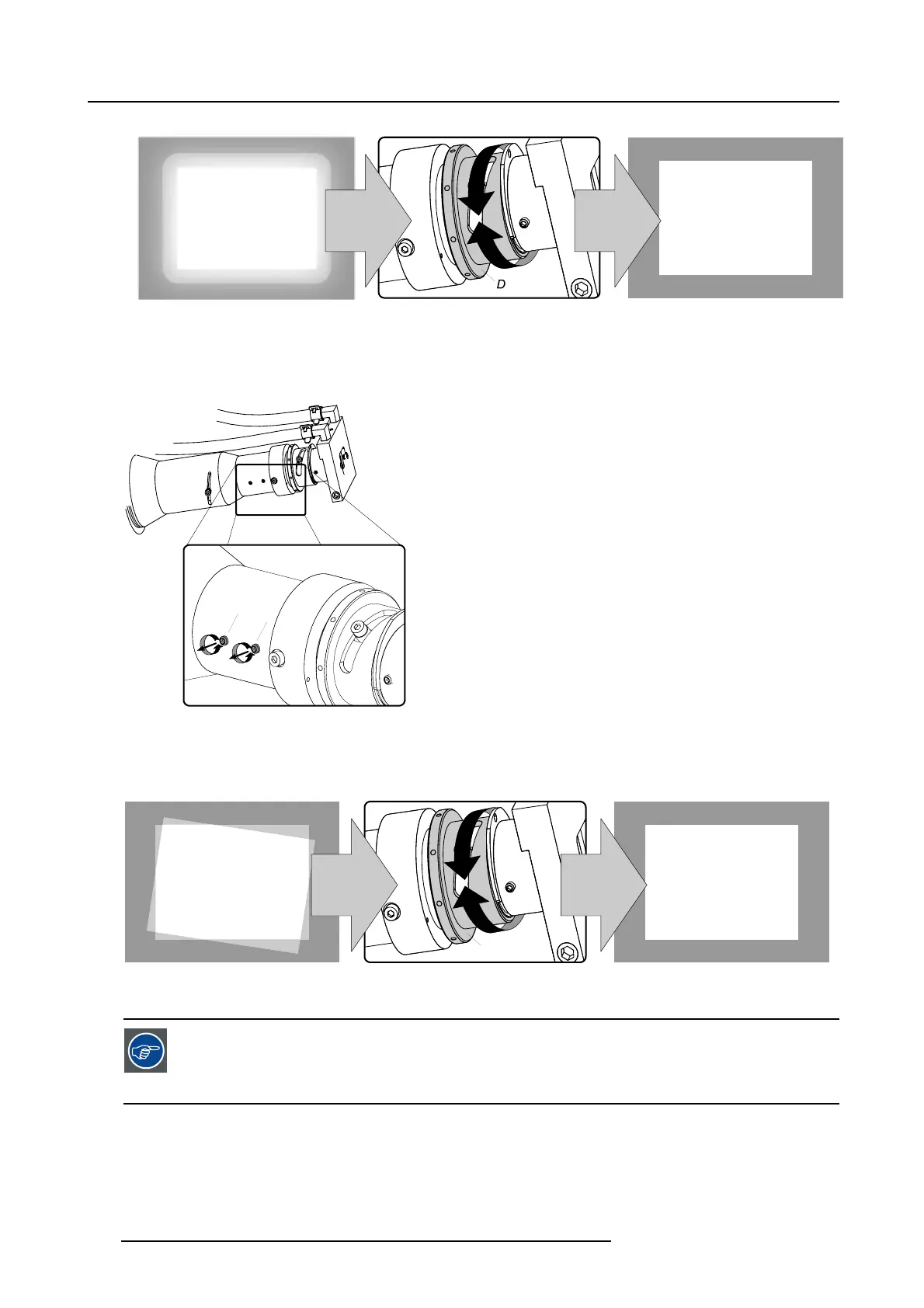
Image 11-15
9. Gently rotate the adjustment ring D until the projected light beam matches the projected outline of the DMD’s.
Note: No spots in the projected image may move along with the movements of the rod. Spots which move with the movements
of the rod indicates that the exit side of the integration rod is contaminated with dust. If this is the case, remove the
integration rod and try to blow away the dust. If this doesn’t help replace the integration rod.
D
Image 11-16
10.Fasten the two set screws A which you released in step 8 and reinstall the projector side cover.
When you are familiar with this adjustment procedure you can optimize the focus position of the rod by first
rotate the rod until you clea
rly see the sloped edges on the screen and then focusing these edges as sharp ad
possible. Then rotate the rod back until the projected light beam matches the projected outline of the DMD’s.
This way of focusing the integration rod has to be done quickly. Otherwise, the sealing between the DMD’s
and the prism will be da
maged.
116 R59770072 FLM SERIES 19/03/2007

 Loading...


