9. Input & communication unit
9. INPUT & COMMUNICATION UNIT
About this chapter
This chapter describes how to replace the complete input & communication unit or one of its input modules. Hot swapping of this
unit is not allowed. Projector must be switched off.
Parts
1
2
3
4
5
6
7
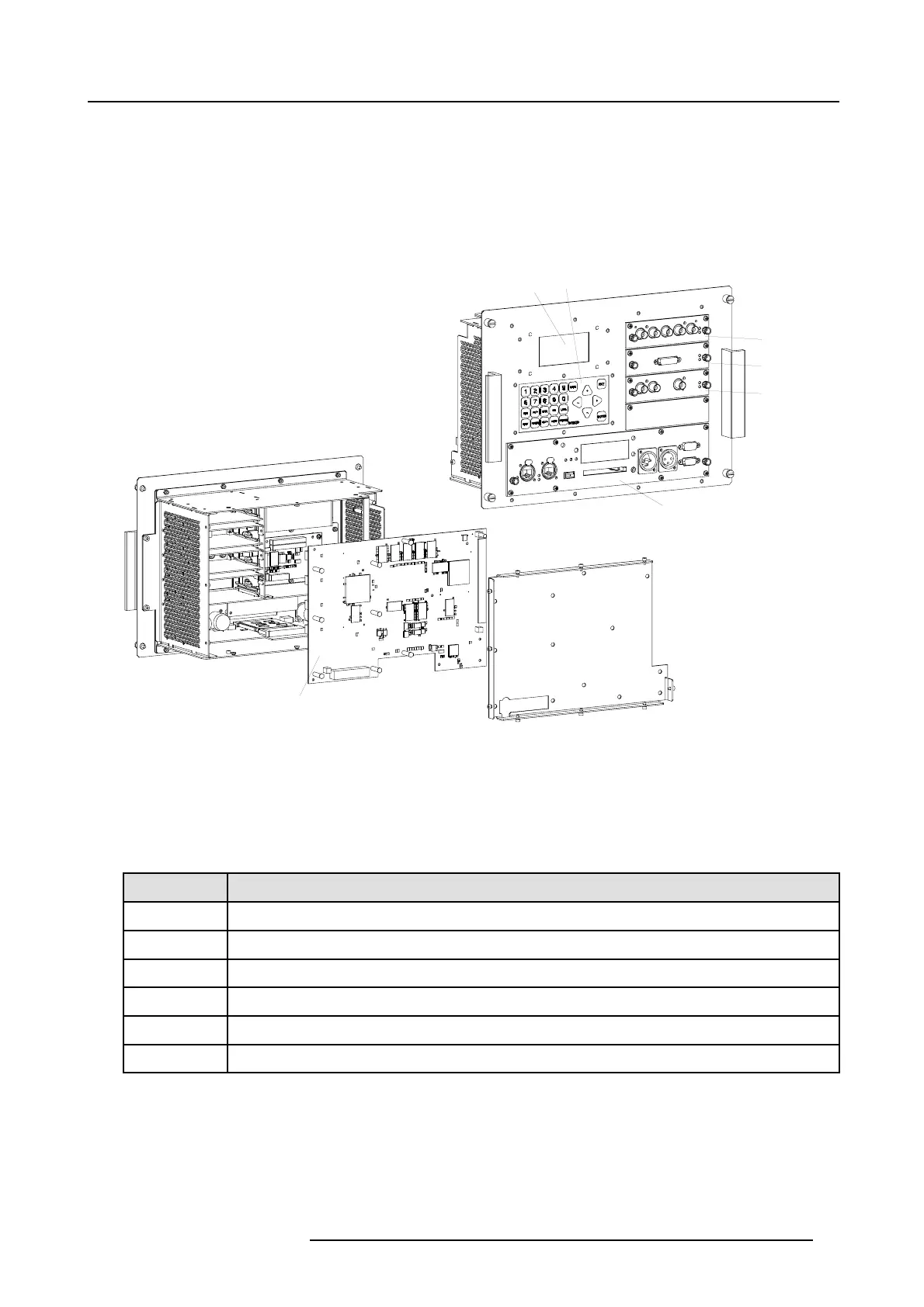
Image 9-1
1 LCD panel.
2 Local key pad.
3 5 Cable input module.
4 DVI input module.
5 HDSDI - SDI input module.
6 Communication unit.
7 Pixel Map Processor (PMP)
Order info
Order number
Description
R848591K
Input & communication unit for FLM R20+
R9854430
5 Cable input module.
R9854440
High bandwidth data input mod
ule (RGB).
R9854450
HDSDI - SDI input module.
R9854460 DVI input module.
R848607
Cover plate for unused input slot.
Overview
• Removal of the input & communication unit
• Installation of the input & communication unit
• Removal of an input module
• Installation of an input module
R59770072 FLM SERIES 19/03/2007
95

 Loading...


