13. Cold mirror assembly
13.4 Adjusting the cold mirror
WARNING: This procedure may only be performed by qualified technical service personnel.
Necessary tools
• Wrench 10 mm
• Wrench 7 mm or nut driver 7 mm
• Light meter
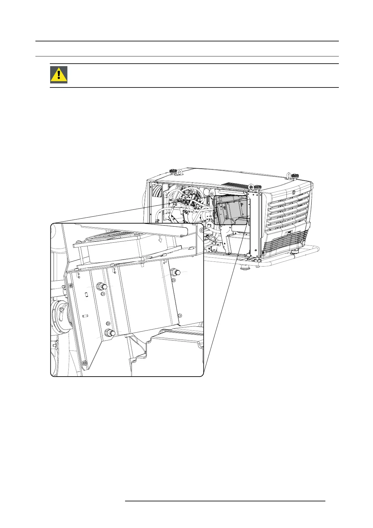
How to adjust the cold mirror?
1. Place the light meter in the center of the image and project a white test pattern.
2. Turn screw 1 and then screw 2 until the maximum light output is measured.
Note: Both screws adjust independently of each other.
1
2
3
A
A
A
Image 13-9
Adjust cold mirror
3. Turn screws 3 one revolution in or out (choose a direction to start) and adjust screw 1 and screw 2 again for maximum light output.
4. Is the new maximum higher than the previous one?
If yes, you adjust in the correct directi
on. Repeat step 3 in the same direction as many times as necessary until the new maximum
is lower then the previous one. Then go to step 5.
If no, you adjust in the wrong direction. Return one revolution and repeat step 3 by turning in the other direction.
5. Turn screw 3 one revolution back.
6. Check the brightness uniformity. In m
ost cases it will be OK.
If not OK, turn slightly on the adjustment screws 1 and 2 until a uniform brightness is obtained.
- Screw 1 will correct the difference between the left and the right side of the projected image.
- Screw 2 will correct the difference betw
een the top and the bottom side of the projected image.
Check again and repeat if necessary.
7. When the adjustment is finished, secure the position by turning the security nuts (A) against the plate (hold on the screws while
securing the nuts).
R59770072 FLM SERIES 19/03/2007
127

 Loading...


