16. FLM liquid cooling circuit
16.2 Introduction
Functionality
Much heat has to be extracted from the DMD’s and from the light pipe entrance during operation of the projector. The liquid cooling
circuit takes care of this. The liquid cooling circuit is a closed loop of flexible tubing comprising of a pump, three cooling blocks for
the DMD’s, a cooling block for the light pipe entrance, a heat exchanger, a pressure vessel and a manometer. The cooling liquid
inside the circuit absorbs the heat of the cooling blocks. Via the pump, the heated-up liquid is transported to the heat exchanger,
which in turn cools down the liquid.
The pressure vessel in the circuit makes it possible to put a small pressure on the cooling liquid. The required pressure
exerted via
the pressure vessel serves to prevent cavitation and hence ensures the good working condition of the pump. Note that the pressure
doesn’t influence the cooling capacity of the system.
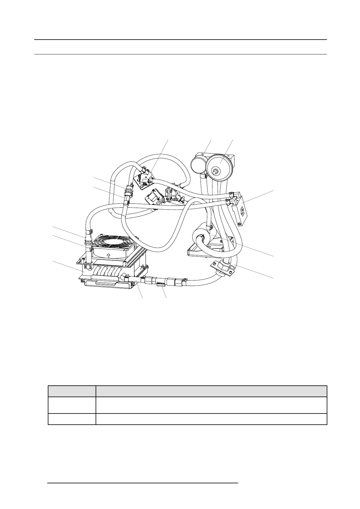
Parts of the liquid cooling circuit
ABC
D
E
F
GH
I
J
K
K
J
Image 16-2
A DMD - Peltier cooling block.
B Manometer.
C Pressure vessel.
D Cooling block light pipe entrance.
EPump.
FOverflowpipe.
G Flow switch.
H Transparent tube for vis
ual check.
I Heat exchanger.
J Female valved fitting.
K Male valved fitting.
Order info liquid c
ooling
Order number
Description
R395198K
Complete liquid cooling refill kit. Includes tubes, valved fittings, syringe, air pump, two plastic bottles of 1
liter filled with cooling liquid.
B1909086K
Four bottles of 1 liter filled with cooling liquid. (no additional tools)
156 R59770072 FLM SERIES 19/03/2007

 Loading...


