21. Pixel map processor board
21.1 Diagnostics
Overview
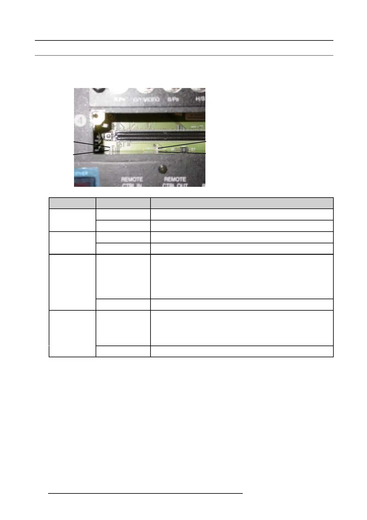
When removing input slot 4, 4 LEDs become visible for diagnostic purposes. Start with the power check LEDs and continue with
the FPGA configuration check LEDs.
LED 0
LED 1
Power OK
Power in O
Image 21-2
LED name
Status
Description
Red
Power supply to the PMP board is OK.Power in OK
Out Power supply to the PMP not OK. Check power supply to PMP.
Red
All on board created voltages are OKPower OK
Out One of the on board created voltages is not OK. Replace the PMP board.
Red
• During start up LED 0 and LED 1 are red. When the FPGAs on the PMP
are correctly configured, LED 0 turns off after a few seconds.
• If it remains red, FPGAs on PMP are not correctly configured.
- Reload software and try again to reconfigure.
- Replace PMP board.
LED 0
Out If both power LEDs are red, then the FPGAs on the PMP are correctly c
onfigured.
Red
• During start up LED 0 and LED 1 are red. When the FPGAs on the FIB are
correctly configured, LED 1 turns off after a few seconds.
• If it remains red, FPGAs on the FIB board are not correctly configured.
Problem is situated on the FIB board.
LED 1
Out If both power LEDs are red, then the FPGAs on the FIB are correctly configured.
212 R59770072 FLM SERIES 19/03/2007

 Loading...


